Non-contact robot joint torque measuring device based on inverse magnetostrictive effect

A robot joint and inverse magnetostriction technology, which is applied in measurement devices, force/torque/work measuring instruments, torque measurement and other directions, can solve the problems affecting the stability of the device and measurement accuracy, complex structure, and low measurement accuracy, etc. Achieve the effects of high-precision real-time dynamic measurement, simple fixed connection structure, and simple measurement principle

Inactive Publication Date: 2018-09-18
HARBIN INST OF TECH
View PDF8 Cites 5 Cited by
  • Summary
  • Abstract
  • Description
  • Claims
  • Application Information

AI Technical Summary

Problems solved by technology

The advantage of this measurement device is that it can realize double-turn measurement and multi-position parallel measurement of torque data, and has high sensitivity; the problem with this measurement device is that the structure is complex, there are multiple probes and multiple wires, which affect the stability and measurement of the device. precision
The advantages of this measurement device are: small size, light weight, and can avoid the influence of factors such as temperature, humidity and electromagnetic noise; the problems of this measurement device are: it is a contact torque measurement device, and there are problems of stability and uncertainty , the measurement accuracy is not high

Method used


Image

  • Non-contact robot joint torque measuring device based on inverse magnetostrictive effect
  • Non-contact robot joint torque measuring device based on inverse magnetostrictive effect
  • Non-contact robot joint torque measuring device based on inverse magnetostrictive effect

Examples


Embodiment 1

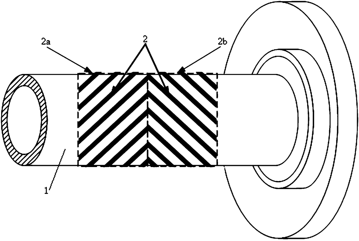
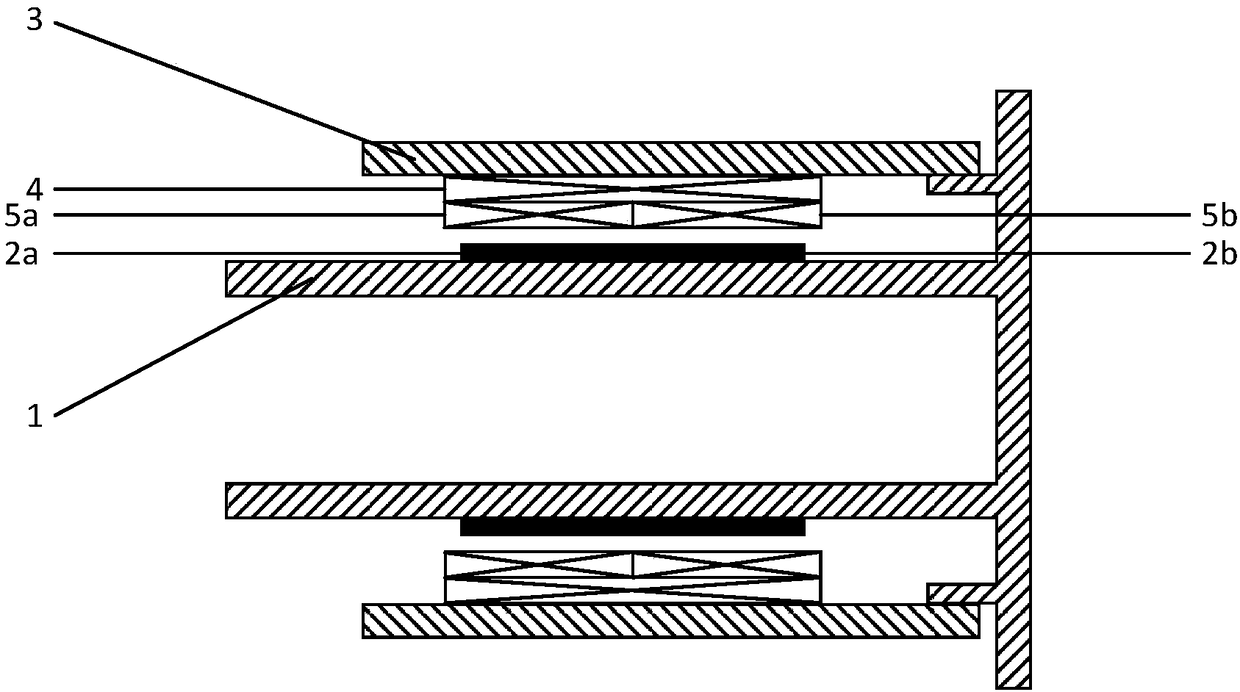
[0036] refer to figure 1 and figure 2 , the non-contact robot joint torque measuring device based on the inverse magnetostrictive effect in the present embodiment, the output shaft 1 of the robot joint torque is coated with a giant magnetostrictive material coating strip 2, and the giant magnetostrictive The stretch material coating strip 2 is divided into a positive giant magnetostrictive material coating strip 2a and a negative giant magnetostrictive material coating strip 2b, and the positive giant magnetostrictive material coating strip 2a and the negative giant magnetostrictive material coating strip 2a The layer strips 2b are coated on the output shaft 1 at equal intervals along the axial left and right symmetry; on the output shaft 1, a sleeve 3 is sleeved on the outer side of the giant magnetostrictive material coating strip 2, and the sleeve 3 An excitation coil 4 is mounted on the inner wall, and a left measurement coil 5a and a right measurement coil 5b of the sam...

Embodiment 2

[0045] refer to figure 1 In this embodiment, on the basis of Embodiment 1, the positive giant magnetostrictive material coating strip 2a is coated on the output shaft 1 with an axial tilt of ﹢ 45°, and the negative giant magnetostrictive material coating strip 2b is applied along the Axially inclined at -45° and applied on output shaft 1.

Embodiment 3

[0047] refer to figure 2 , the lengths of the left measuring coil 5 a and the right measuring coil 5 b along the axis are set equal to 1 / 2 of the length of the excitation coil 4 along the axis.


PUM


Abstract

The invention relates to a non-contact robot joint torque measuring device based on the inverse magnetostrictive effect and belongs to the sensing measurement technology of robot robotic arm precisioncontrol. The measuring device is characterized in that an output shaft of the robot joint torque is coated with giant magnetostrictive material coating strips, the giant magnetostrictive material coating strips comprise positive giant magnetostrictive material coating strips and negative giant magnetostrictive material coating strips, the positive giant magnetostrictive material coating strips and the negative giant magnetostrictive material coating strips are obliquely coated on the output shaft at equal intervals along the axial direction symmetrically left and right, a sleeve is sleeved onthe output shaft on the outer side of the giant magnetostrictive material coating strips, an excitation coil is mounted on an inner wall of the sleeve, and left and right measuring coils in the samespecification are mounted side by side on the inner wall of the excitation coil in the axial direction. The measuring device is advantaged in that high-accuracy high-precision real-time dynamic measurement of the torque is carried out without touching a driving shaft and without changing the force condition of the driving shaft and rotary and dynamic working conditions, and thereby precise controlon robot arms is realized.

Description

technical field [0001] The invention belongs to the sensing and measuring technology for the precision control of a robot manipulator, and mainly relates to a non-contact robot joint torque measuring device based on an inverse magnetostrictive effect. Background technique [0002] As an important component of the robot, the performance of the robot joint directly affects the overall performance of the robot. In actual work, the end of the robot is required to move along the specified trajectory at a specified speed and acceleration under certain load conditions. And this mainly depends on whether each joint system can dynamically provide the required driving force or torque. With the application and development of robots in the fields of industry, military, service, medical care and aerospace, the requirements for the control of robotic arms are getting higher and higher. Precise control to complete a series of maintenance actions; the pen tip of the drawing robot must keep...

Claims


Application Information

Patent Timeline
Patent Type & Authority Applications(China)
IPC IPC(8): G01L3/10G01L5/00
Inventor 王静王雷唐钰璇
Owner HARBIN INST OF TECH
Why Eureka
Try Eureka