Nonlinear correction method for piezoelectric ceramic tube scanner

A piezoelectric ceramic tube, nonlinear correction technology, applied in scanning probe technology, instruments, scientific instruments, etc., can solve the problems of scanning pattern distortion, uneven outer wall electrode segmentation, uneven tube wall thickness, etc., to eliminate scanning The effect of image distortion

Inactive Publication Date: 2004-11-10
INST OF ELECTRICAL ENG CHINESE ACAD OF SCI
View PDF0 Cites 7 Cited by
  • Summary
  • Abstract
  • Description
  • Claims
  • Application Information

AI Technical Summary

Problems solved by technology

In addition, due to the uneven division of the outer wall electrode and the uneven thickness of the tube wall during the processing of the piezoelectric ceramic tube, the movement driven by the X and Y direction voltages cannot be

Method used


Image

  • Nonlinear correction method for piezoelectric ceramic tube scanner
  • Nonlinear correction method for piezoelectric ceramic tube scanner
  • Nonlinear correction method for piezoelectric ceramic tube scanner

Examples


Embodiment

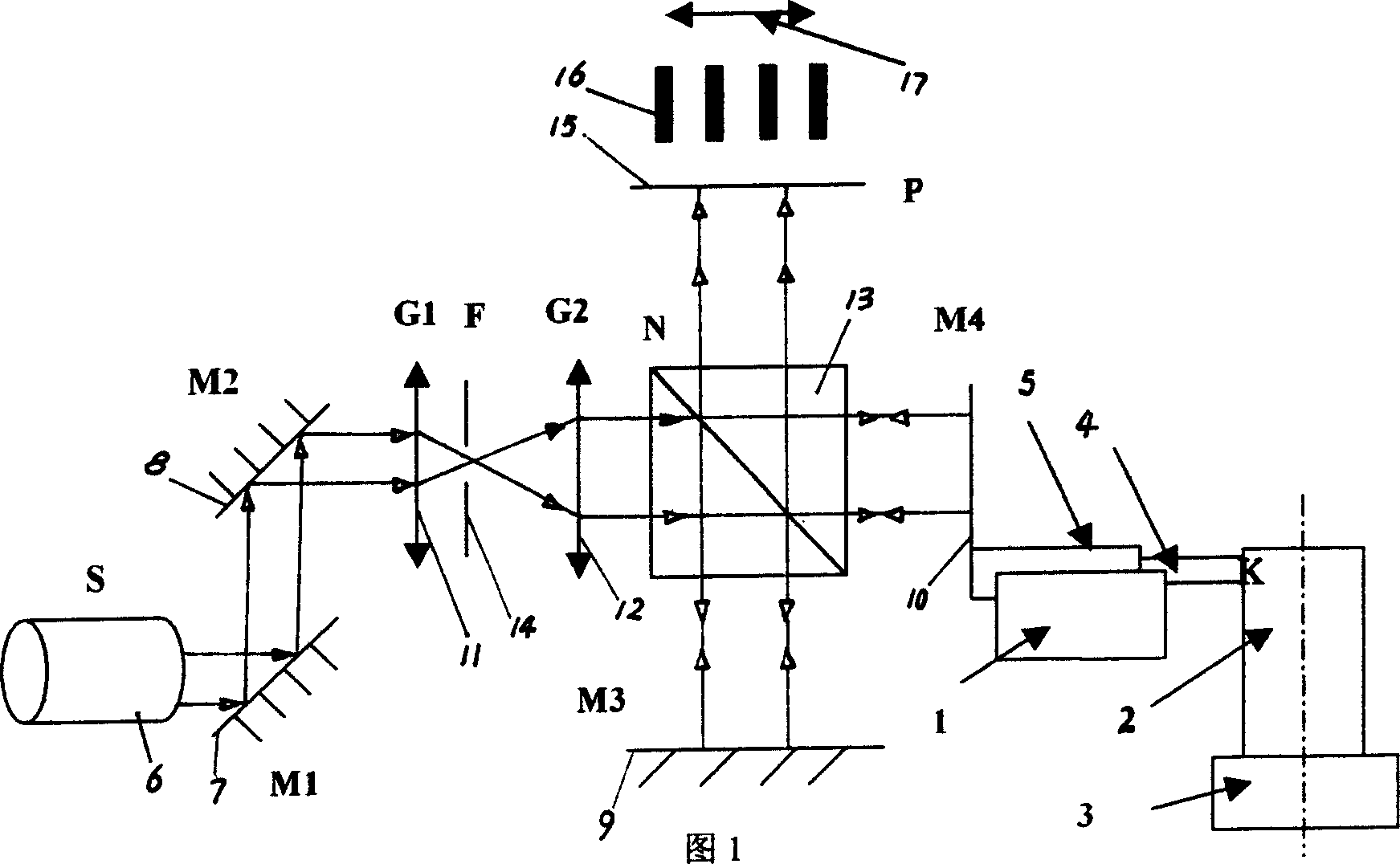
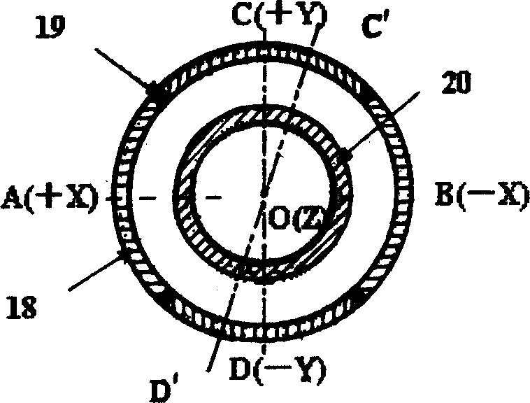
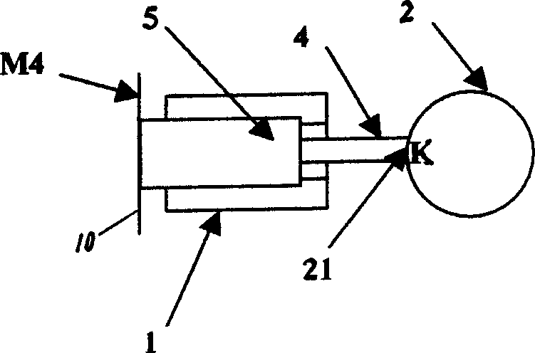
[0032] Figure 1, figure 2 with image 3 As shown, the stretching amount of the piezoelectric ceramic tube scanner of the present invention is measured using a Michelson interference device, wherein the mark 6 is a laser tube S, and the marks 7, 8, 9, and 10 are respectively plane mirrors M1, M2, M3, M4, Marks 11 and 12 are convex lenses G1 and G2 respectively, mark 14 is filter mirror F, mark 13 is beam splitter N, mark 15 is receiving screen P, mark 16 is interference fringes, mark 17 is moving direction of interference fringes, mark 18 is compression The metal coating on the outer wall of the electric ceramic tube, the mark 19 is the insulating layer, the mark 20 is the metal coating on the inner wall of the piezoelectric ceramic tube, the mark 21 is the contact point K, and the sliding table 1, the piezoelectric ceramic tube 2, the rotating table 3 and the connecting rod 4. Among them, the requirements are: the piezoelectric ceramic tube 2 is fixed on the rotary table 3 a...


PUM


Abstract

The invention provides a piezoelectric ceramic tube scanner nonlinear correcting method, able to effectively eliminate scanned picture distortion when scanning pictures by using piezoelectric ceramic tube, thus beneficial to obtain real scanned pictures of actual surface appearance of an object. Its technical project is a nonlinear correcting method for piezoelectric ceramic tube scanner, and its character: (1) adopting micrometer to measure a series of corresponding data between the stroke and driving voltage of the piezoelectric ceramic tube; (2) it fits the curve made by these data into a stroke-driving voltage relationship curve.

Description

technical field [0001] The invention relates to the precise imaging technology of a scanning probe microscope, which is a nonlinear correction method for a piezoelectric ceramic tube scanner. Background technique [0002] The piezoelectric ceramic tube scanner is one of the main moving parts of the scanning probe microscope. It drives the probe or sample to scan in the X and Y directions and move in the Z-axis direction, thereby completing the imaging of the surface topography of the sample. The piezoelectric ceramic tube used for the scanner has the following structural characteristics: After the inner surface and the outer surface are metallized, they are polarized in the radial direction, and the metal coating on the outer wall is divided into four electrodes as scanning electrodes for horizontal X and vertical Y. The entire inner wall of the tube serves as a Z-direction electrode for adjusting the height of the needle tip. Due to the inherent hysteresis characteristic o...

Claims


Application Information

Patent Timeline
IPC IPC(8): G01N13/00G01Q40/00
Inventor 王丹丹左燕生韩立安秉谦林云生
Owner INST OF ELECTRICAL ENG CHINESE ACAD OF SCI
Why Eureka
Try Eureka