Pneumatic vibration test device and method

A technology of pneumatic vibration and test device, applied in vibration test, measurement device, test of machine/structural components, etc., can solve the problems of large equipment occupation, complex power device, high cost, convenient installation and disassembly, and large adjustment range 、Easy to install and disassemble

Active Publication Date: 2018-09-18
SHANGHAI JIAO TONG UNIV
View PDF8 Cites 0 Cited by
  • Summary
  • Abstract
  • Description
  • Claims
  • Application Information

AI Technical Summary

Problems solved by technology

Its shortcomings are: 1) the structure of the test bench is complicated (including large parts such as gearboxes and clutches), the cost is high, and the equipment occupies a large area; 2) the operation of the test bench is complicated and inconvenient to carry; 3) the processing method High energy consumption and high cost
Its shortcomings are: 1) the test bench and its external power device are complex and costly; 2) the vibration frequency of the test bench is low, and it is mostly used to simulate the low-frequency vibration environment of some products during transportation, and is used to test automobiles, Shock resistance of product structures such as toys, furniture, and packaging; 3) This processing method consumes a lot of energy
[0006] In small-scale vibration tests, such as sediment vibration rheology, vibration rheology of other materials, chip welding vibration tests, etc., the general experimental conditions have the following characteristics: the number of times the test is used is limited, and the mechanical parameters during the vibration process need to be measured in real time , need vibration equipment and testing equipment to be easily disassembled, etc., but the existing vibration equipment is large in size and complex in structure, making it inconvenient to install mechanical and other external testing equipment, so the test of relevant parameters is mostly to take down the test sample after vibration and install it in the Testing on external testing equipment cannot reflect the impact of vibration on the sample in real time. This problem is particularly prominent in the field of rheology, and vibration equipment is expensive.

Method used


Image

  • Pneumatic vibration test device and method

Examples


Embodiment Construction

[0035] The present invention will be described in detail below in conjunction with specific embodiments. The following examples will help those skilled in the art to further understand the present invention, but do not limit the present invention in any form. It should be noted that those skilled in the art can make several modifications and improvements without departing from the concept of the present invention. These all belong to the protection scope of the present invention.

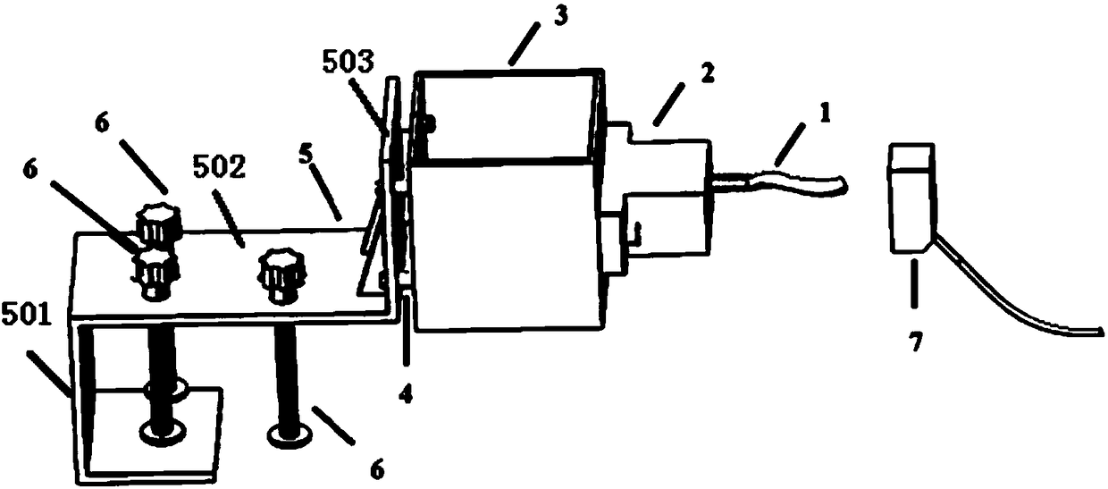
[0036] Such as figure 1 As shown, a schematic diagram of a preferred embodiment of a pneumatic vibration test device, including:

[0037] Pneumatic vibrator 2 is used to provide vibration air pressure for testing; the pneumatic vibrator is provided with air intake components, and the air intake components are connected to air supply equipment;

[0038] The vibrating table 3 is used to accommodate the test piece to be tested. The vibrating table 3 is connected and fixed with the pneumatic vibrator...


PUM


Abstract

The invention provides a pneumatic vibration test device and method; the test device comprises a pneumatic vibrator used for providing a vibration air pressure for the test; the pneumatic vibrator hasan air inlet part connected with an air supply device; the test device also comprises a vibration table used for containing a to-be-detected member; the vibration table is fixedly connected with thepneumatic vibrator; the vibrations of the pneumatic vibrator are transferred to the vibration table, and the vibration table drives the to-be-detected member to vibrate; the test device also comprisesa mount base used for mounting and fixing the vibration table. The pneumatic vibration test device is easy to mount and dismount, large in a controllable scope of the vibration frequency (0.1Hz to 400Hz) and amplitude (0-5mm), can be repeatedly used, and is low in cost.

Description

technical field [0001] The present invention relates to a vibration test device and method, in particular to a test device and method which are generated by air flow and can provide a relatively large range of controllable vibration frequency and vibration amplitude. Background technique [0002] Existing vibration test benches are divided into electric vibration test benches, mechanical vibration test benches and hydraulic vibration test benches. The mechanical vibration table belongs to the low-frequency large-load vibration test bench, the frequency is 5-80Hz, the load is from 50Kg-1000Kg, the displacement is about 5mm, and the acceleration is 3-20g; it is suitable for low-frequency experiments, and the frequency does not meet the requirements. The electrodynamic vibration test bench is a high-frequency, large displacement, and large thrust vibration test bench. The frequency range is 5 to 3000 Hz, and the displacement can reach 25.4mm. , due to the large structure of th...

Claims


Application Information

Patent Timeline
Patent Type & Authority Applications(China)
IPC IPC(8): G01M7/02
CPCG01M7/022G01M7/027
Inventor 喻国良王呈
Owner SHANGHAI JIAO TONG UNIV
Why Eureka
Try Eureka