
Plasma gas sensor and manufacturing method thereof

A gas sensor and plasma technology, applied in the field of ions, can solve problems such as signal instability, lower working voltage, and sensor damage, and achieve the effects of improved ability and efficiency, lower working voltage, and enhanced electrical signals

Active Publication Date: 2022-02-08
SHANGHAI JIAOTONG UNIV
View PDF0 Cites 0 Cited by
  • Summary
  • Abstract
  • Description
  • Claims
  • Application Information

AI Technical Summary

Problems solved by technology

For example, in terms of electrodes, one-dimensional nanomaterials such as carbon nanotubes are introduced as the discharge center of the electrode surface to exert its electric field concentration effect, but because the growth of one-dimensional nanomaterials is generally dense and unnecessary, the distance between nanomaterials is very small. It is small, so it is easy to produce electric field shielding effect, which limits the reduction of its working voltage; in addition, a large area of ​​one-dimensional nanomaterials is introduced into the sensor structure, and only a small part of the gas discharge signal is generated, which affects the working efficiency and structural stability of the sensor. sex is a challenge
In terms of discharge space gap, the parallelism between electrodes is very important for electrode pairs at the macro scale, because the protrusion or inclination of the electrode surface will cause partial discharge current injection, resulting in signal instability and sensor damage; However, whether it is a parallel plate electrode or a coaxial cylindrical electrode, it is a technical problem to control and maintain the parallelism at the microscopic scale. At the same time, with the continuous reduction of the discharge gap, the circulation of the gas to be measured will constitute a new technical issues

Method used


Image

  • Plasma gas sensor and manufacturing method thereof
  • Plasma gas sensor and manufacturing method thereof
  • Plasma gas sensor and manufacturing method thereof

Examples


Embodiment Construction

[0037] The plasma gas sensor and its manufacturing method proposed by the present invention will be further described in detail below with reference to the drawings and specific embodiments. Advantages and features of the present invention will be apparent from the following description and claims. It should be noted that all the drawings are in a very simplified form and use imprecise scales, and are only used to facilitate and clearly assist the purpose of illustrating the embodiments of the present invention.

[0038] Before proposing the present invention, the inventor of the present application has carried out sufficient research to the present possible plasma gas sensor, and concrete research is as follows:

[0039] 1) The electrode size of the reported plasma gas sensor is at the macroscopic level of millimeters or above. Since it is difficult to achieve absolute parallelism and consistency in the microscopic structure, the functional area that actually generates gas di...


PUM

PropertyMeasurementUnit
diameteraaaaaaaaaa
widthaaaaaaaaaa
thicknessaaaaaaaaaa

Abstract

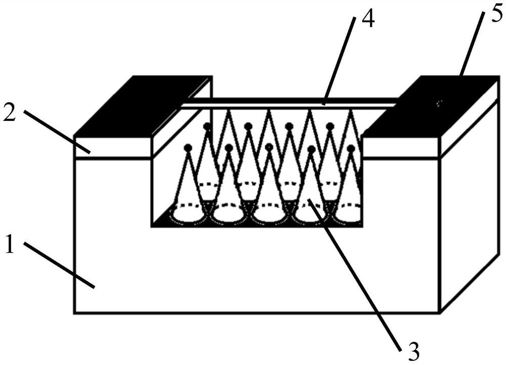
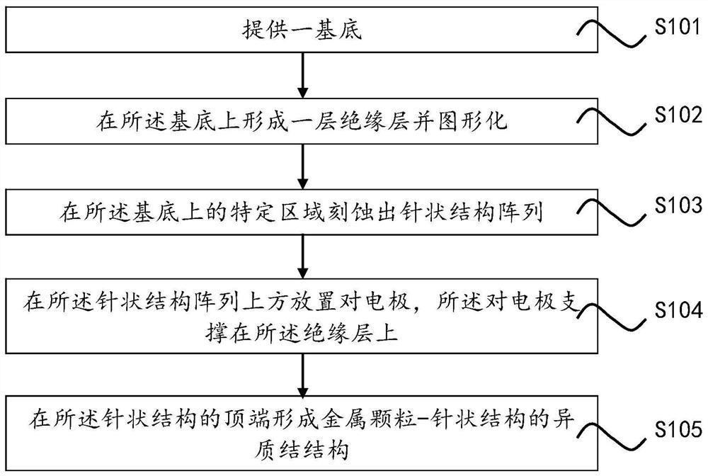
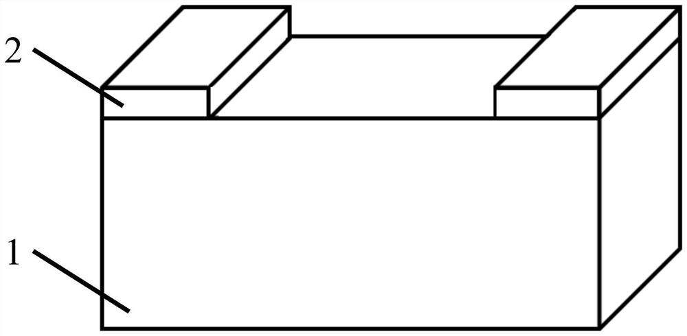
The invention discloses a plasma gas sensor and a manufacturing method thereof. The gas sensor comprises a substrate, an insulating layer, a needle-like structure array formed on the substrate, and a counter electrode, wherein the counter electrode is arranged above the needle-like structure, and is formed by the insulating layer. A gas discharge space is isolated and formed, and the tops of several needle-like structures in the needle-like structure array form a heterojunction structure with metal particles. This structure makes full use of the microscale system composed of the counter electrode, needle-like structure, and insulating layer gap, in which the needle-like structure and the counter electrode reflect the electric field concentration effect, and the nanoscale discharge space improves the charge conduction efficiency generated by gas discharge. , which facilitates the acquisition of gas sensing signals. The plasma gas sensor cleverly realizes the local strong electric field required for plasma generation, takes advantage of the small-scale advantage in the transmission process, and achieves technical effects such as device miniaturization, low operating voltage, and low power consumption. The manufacturing method of the structure has less consumables and a high structure utilization rate, and achieves high-efficiency, economical and precise micro-machining effects.

Description

technical field [0001] The invention relates to the field of plasma technology, in particular to a plasma gas sensor and a manufacturing method thereof. Background technique [0002] Plasma is called the fourth state of matter, which is mainly formed by the separation of positive and negative ions (electrons) in gas under the condition of energy injection. As a way of energy injection, when a higher voltage is applied to form a stronger electric field, gas discharges and plasmas can only occur under the action of different types and contents of gases higher than a specific electric field, which is manifested in the circuit. current signal. Therefore, according to the different and specific loading voltage required under different gas conditions, that is, the threshold voltage, it can be used as a sensing signal for judging the gas type, content and other information. The device based on the above principle is called a plasma gas sensor. However, the traditional electric fi...

Claims


Application Information

Patent Timeline
Patent Type & Authority Patents(China)
IPC IPC(8): G01N27/70G01N27/62
CPCG01N27/62G01N27/70
Inventor 刘海侯中宇
Owner SHANGHAI JIAOTONG UNIV
Learn More