
Display panel, manufacturing method thereof, and display device

A technology for display panels and display devices, which is used in the manufacture of semiconductor/solid-state devices, semiconductor devices, electrical components, etc., and can solve the problems of asynchronous data signal lines, different number of pixels, affecting the display uniformity of display panels, etc. Uniformity, guaranteed synchronization effect

Active Publication Date: 2018-09-18
KUNSHAN GO VISIONOX OPTO ELECTRONICS CO LTD
View PDF3 Cites 11 Cited by
  • Summary
  • Abstract
  • Description
  • Claims
  • Application Information

AI Technical Summary

Problems solved by technology

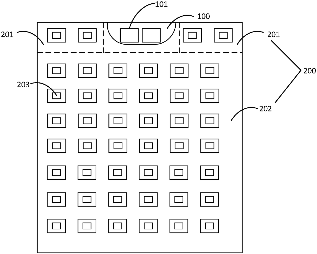
[0003] In the process of realizing the traditional technology, the applicant found at least the following problems: the display area is no longer a regular rectangle due to the slotting of the display panel, the slotted area no longer contains pixels and corresponding driving circuits, and the number of pixels in each row is different. The loads of the scanning signal lines of different rows of pixels are no longer the same, and the data signal lines are not synchronized when writing data to the pixels, which affects the display uniformity of the display panel

Method used


Image

  • Display panel, manufacturing method thereof, and display device
  • Display panel, manufacturing method thereof, and display device
  • Display panel, manufacturing method thereof, and display device

Examples


Embodiment Construction

[0051] In order to facilitate the understanding of the present invention, the present invention will be described more fully below with reference to the associated drawings. Preferred embodiments of the invention are shown in the accompanying drawings. However, the present invention can be embodied in many different forms and is not limited to the embodiments described herein. On the contrary, these embodiments are provided to make the understanding of the disclosure of the present invention more thorough and comprehensive.

[0052] It should be noted that when an element is referred to as being “fixed” to another element, it can be directly on the other element or there can also be an intervening element. When an element is referred to as being "connected to" another element, it can be directly connected to the other element or intervening elements may also be present. The terms "vertical," "horizontal," "left," "right," and similar expressions are used herein for purposes ...


PUM


Abstract

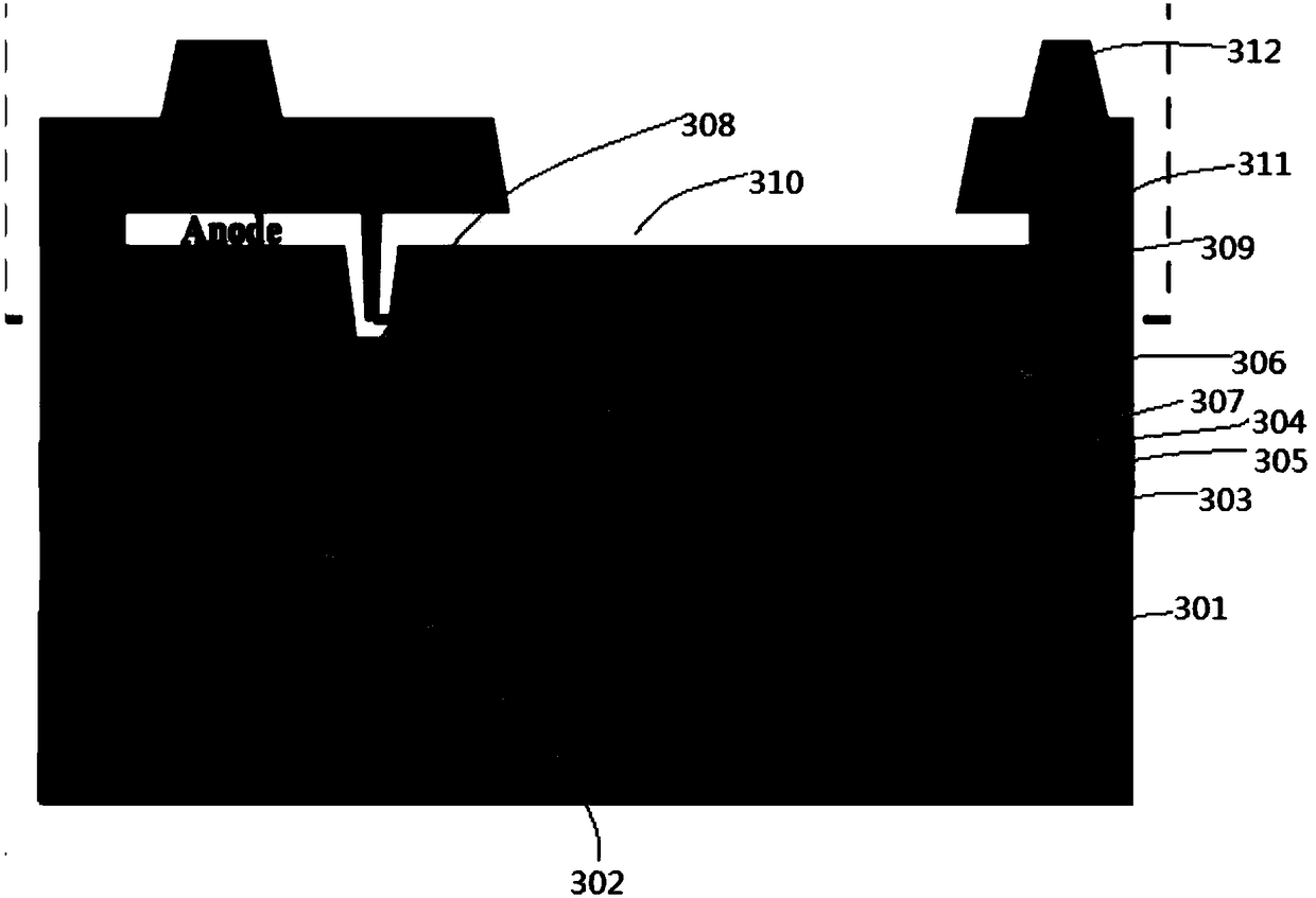
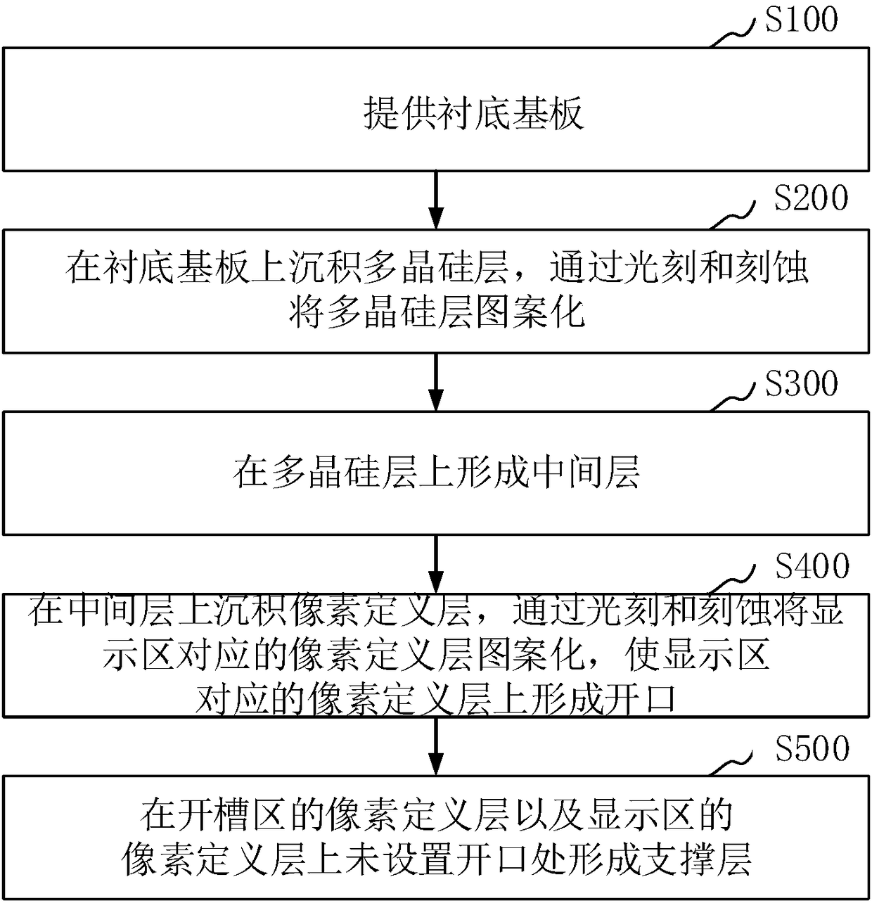
The invention relates to a display panel, a manufacturing method thereof, and a display device. The display panel comprises a display region and a grooved region. The display region comprises multiplerows of pixels. The pixels are formed by evaporating organic light emitting layers at an aperture of a pixel definition layer of the display region. The aperture ratio of the pixel definition layer of the grooved region is zero. According to the invention, TFT back plate structures are simultaneously set on the display region and the grooved region, and in a way of allowing the aperture ratio ofthe pixel definition layer corresponding to the grooved region to be zero, it is ensured that the load of scanning signal lines of pixel rows where the pixel region is located is the same as the loadof scanning signal lines of other pixel rows; synchronism of writing data into the pixels by data signal lines is ensured and uniformity of displaying of the display panel is ensured.

Description

technical field [0001] The present invention relates to the field of display technology, in particular to a display panel, a manufacturing method thereof, and a display device. Background technique [0002] With the development of display technology, in order to realize functions such as Selfie and video call of mobile electronic devices, the display panel is usually provided with slots on the upper side for setting the camera and peripheral driving circuits. The area where the display panel is used to realize image display is the display area, and the area where the display panel is slotted is the non-display area. The pixels distributed in an array in the display area are connected to the scanning signal line and the data signal line through the switching element. The scanning signal output by the scanning signal line is used to control the opening and closing of the switching element, and the data signal output by the data signal line is used to drive the pixel display. ...

Claims


Application Information

Patent Timeline
Patent Type & Authority Applications(China)
IPC IPC(8): H01L27/32H01L21/77
CPCH01L21/77H10K59/123
Inventor 张成成段培朱晖张九占
Owner KUNSHAN GO VISIONOX OPTO ELECTRONICS CO LTD
Learn More