

Button cell with base
A button battery and electrolyte technology, which is applied to battery components, battery boxes/coats, circuits, etc., can solve the problems of shortening battery life, reducing the overall stability of the battery and anti-leakage performance, etc., to achieve extended use Longer life, extended operating temperature range, and improved overall stability
- Summary
- Abstract
- Description
- Claims
- Application Information
AI Technical Summary
Problems solved by technology
Method used
Image

Examples
Embodiment 1
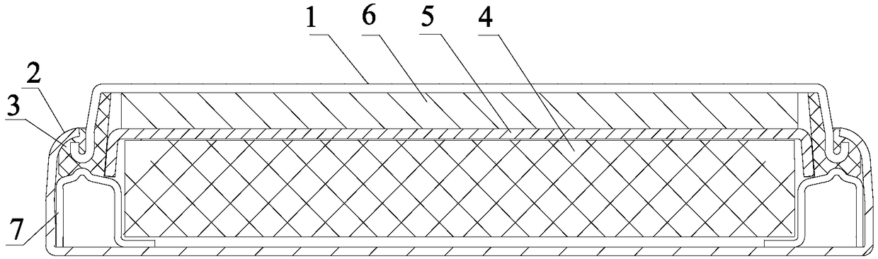
[0045] see Figure 1 to Figure 7 , a button battery with a base provided in the embodiment of the present invention, including a negative electrode cover 1, a positive electrode casing 2, a sealing ring 3, a positive electrode 4, a diaphragm 5, a negative electrode 6 and an electrolyte, wherein the sealing ring 3 is hermetically connected to the negative electrode cover 1 and the positive electrode casing 2, and the negative electrode cover 1 and the positive electrode casing 2 form a sealed cavity, and the positive electrode 4, the separator 5, the negative electrode 6 and the electrolyte are arranged in the sealed cavity; the button battery also includes The energy gathering ring 7 arranged in the positive electrode casing 2; the energy gathering ring 7 includes an outer ring wall 71, an inner ring wall 72, and a top wall 73 for connecting the outer ring wall 71 and the inner ring wall 72, and the outer ring wall 71. The inner ring wall 72 and the top wall 73 form an annular...
Embodiment 2
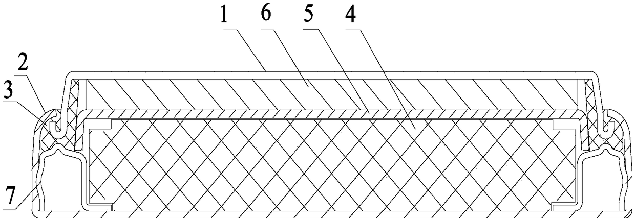
[0090] Based on the same inventive concept as the previous embodiment, this embodiment provides a button battery model of improved CR2032, the structure of the improved CR2032 button battery please refer to figure 2 , Figure 5 , Figure 6 and Figure 7 , including: negative electrode cover 1, positive electrode casing 2, sealing ring 3, positive electrode 4, diaphragm 5, negative electrode 6 and electrolyte, wherein, sealing ring 3 is hermetically connected negative electrode cover 1 and positive electrode casing 2, and makes the negative electrode cover 1 and the positive electrode casing 2 form a sealed cavity, and the positive electrode 4, the diaphragm 5, the negative electrode 6 and the electrolyte are arranged in the sealed cavity; the button battery also includes an energy gathering ring 7 arranged in the positive electrode casing 2; The energy gathering ring 7 includes an outer ring wall 71, an inner ring wall 72 and a top wall 73 for connecting the outer ring wall...
Embodiment 3
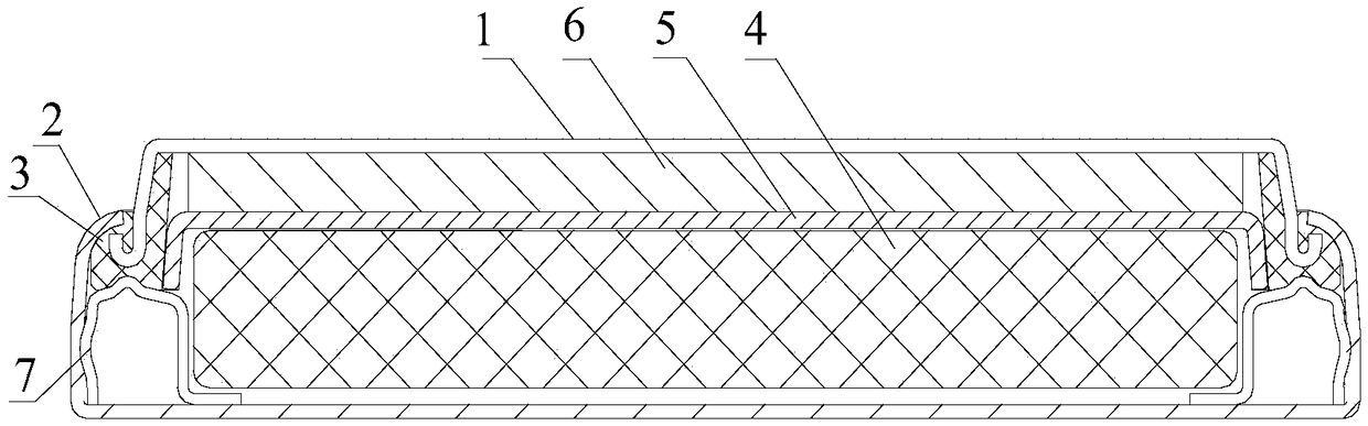
[0114] Based on the same inventive concept of the previous embodiment, this embodiment provides a button battery whose model is improved CR2450, see figure 2 , Figure 6 and Figure 8, including: negative electrode cover 1, positive electrode casing 2, sealing ring 3, positive electrode 4, diaphragm 5, negative electrode 6 and electrolyte, wherein sealing ring 3 is hermetically connected negative electrode cover 1 and positive electrode casing 2, and makes the The negative cover 1 and the positive casing 2 form a sealed cavity, and the positive electrode 4, the diaphragm 5, the negative electrode 6 and the electrolyte are arranged in the sealed cavity; 7. The energy gathering ring 7 includes an outer ring wall 71, an inner ring wall 72 and a top wall 73 for connecting the outer ring wall 71 and the inner ring wall 72, and the outer ring wall 71, the inner ring wall 72 and the top wall 73 form The opening faces the annular groove at the bottom of the positive electrode casin...
PUM
| Property | Measurement | Unit |
|---|---|---|
| Outer diameter | aaaaa | aaaaa |
| The inside diameter of | aaaaa | aaaaa |
| Height | aaaaa | aaaaa |
Abstract
Description
Claims
Application Information