Fixing device for oral cavity, dental jaw tracker and implantation navigation system

A fixation device, oral technology, applied in surgical navigation systems, dentistry, dental implants, etc., can solve the problems of displacement or loosening of the fixation device, cumbersome process of the fixation device, and difficulty in ensuring the sterilization effect. The effect of shortening the implantation treatment cycle and improving the implantation success rate

Active Publication Date: 2018-09-21
SUZHOU DIKAIER MEDICAL TECH
View PDF10 Cites 9 Cited by
  • Summary
  • Abstract
  • Description
  • Claims
  • Application Information

AI Technical Summary

Problems solved by technology

This method requires the operating room to be specially equipped with a water bath device, and it will be difficult to ensure the sterilization effect of the fixture after the water bath is heated; because the thermoplastic material has poor fluidity even if it becomes soft, it is difficult to use the undercut of the tooth to make the fixture firmly stuck in the tooth. On the teeth; the thermoplastic material is hotter before it solidifies, which can irritate the teeth of some patients
[0015] (3) The fixture used in the jaw tracker of ClaroNav in the United States (refer to patent application WO2016090476) is made of pure thermoplastic material. After the device is heated in a water bath, it will be difficult to ensure the sterilization effect; because even if the thermoplastic material becomes soft, the fluidity is poor, and it is difficult to use the tooth undercut to make the fixing device firmly stuck on the tooth, and the lips are pushed against the connecting rod to easily fix it. The device is displaced or loosened, which affects the accuracy of implantation

Method used


Image

  • Fixing device for oral cavity, dental jaw tracker and implantation navigation system
  • Fixing device for oral cavity, dental jaw tracker and implantation navigation system
  • Fixing device for oral cavity, dental jaw tracker and implantation navigation system

Examples


Embodiment Construction

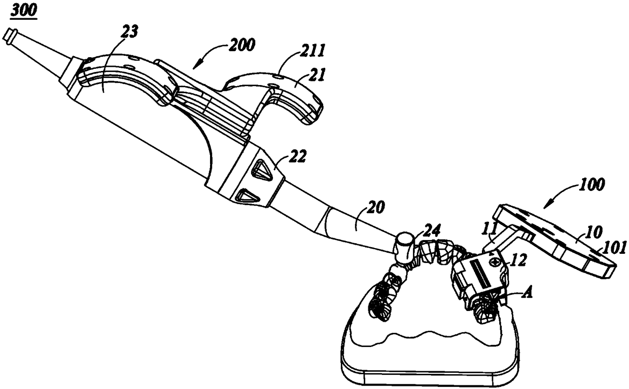
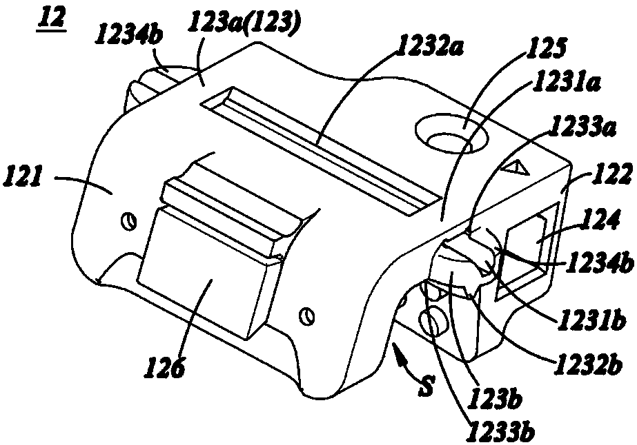
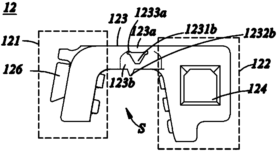
[0037] The present invention will be described in detail below in conjunction with specific embodiments shown in the accompanying drawings. However, these embodiments do not limit the present invention, and any structural, method, or functional changes made by those skilled in the art according to these embodiments are included in the protection scope of the present invention.

[0038] In each drawing of the present application, some dimensions of structures or parts are exaggerated relative to other structures or parts for convenience of illustration, and therefore, are only used to illustrate the basic structure of the subject matter of the present application.

[0039] In addition, terms used herein such as "upper", "above", "under", "below", etc. to express relative positions in space are for convenience of description to describe a unit or feature as shown in the drawings relative to A relationship to another cell or feature. The terms of spatial relative position may be...


PUM


Abstract

The invention discloses a fixing device for an oral cavity, a dental jaw tracker and an implantation navigation system. The fixing device comprises a first part, a second part and a connecting part for connecting the first part with the second part; the first part, the second part and the connecting part form a clamping space to clamp teeth in a non-implantation region; when the fixing device is in a clamped state, the connecting part is in an initial state; when the fixing device is in a removed state, the connecting part changes from the initial state to a deformation state to assist the first part and the second part in separation. The fixing device disclosed by the invention has the following advantages: (1) the fixing device can firmly fix the teeth in the non-implantation region andis hard to loosen, so that the navigation accuracy is improved; (2) a technician does not need to manufacture extra accessories; the implantation operation can be performed on the day, so that the implantation treatment period is shortened; (3) after a fixing device package is sterilized, the fixing device is unpacked and directly used; water bath heating is not needed, so that the risk of surgical infection is reduced, and the implantation success rate is increased; (4) the removal process is simple and convenient.

Description

technical field [0001] The invention relates to the field of medical devices, in particular to a fixation device for the oral cavity, a jaw tracker and an implant navigation system. Background technique [0002] The traditional dental implant surgery is to take a panoramic film of the patient before the operation. The doctor can roughly judge whether the patient's tooth loss can be repaired by implantation by observing the panoramic film, and roughly determine the diameter of the implant and the bone mass displayed on the panoramic film. length. [0003] However, due to the inability of panoramic films to accurately provide the patient's bone information and the limitation of doctors' clinical experience, doctors often need to measure on-site during the operation, but this is limited to the mesial-distal length of the jaw in the edentulous area and the bone The width of the bone cannot be measured, and the doctor’s blind operation is prone to errors, resulting in nerve dama...

Claims


Application Information

Patent Timeline
Patent Type & Authority Applications(China)
IPC IPC(8): A61C8/00A61B34/20A61B17/16A61B17/17
CPCA61B17/1662A61B17/1703A61B17/1739A61B34/20A61B2034/2065A61C8/0089
Inventor 罗哲郁峰陈云何凯
Owner SUZHOU DIKAIER MEDICAL TECH
Why Eureka
Try Eureka