Medicinal liquid shaking device

A liquid medicine and shell technology, applied in the field of liquid medicine shaking device, can solve the problems of complex structure of the device, cumbersome operation, and reduce the work intensity of medical staff, so as to achieve the effects of reducing manpower, speeding up mixing, and improving efficiency

Inactive Publication Date: 2018-09-21
WUHU NOKAN BIOTECH
View PDF12 Cites 1 Cited by
  • Summary
  • Abstract
  • Description
  • Claims
  • Application Information

AI Technical Summary

Problems solved by technology

The medicinal liquid shaking device and the automatic dispensing system, through the first driving part and the second driving part, make the medicinal liquid fully oscillate, can effectively shake the medicinal liquid, an

Method used


Image

  • Medicinal liquid shaking device
  • Medicinal liquid shaking device
  • Medicinal liquid shaking device

Examples


Example Embodiment

[0020] Example 1

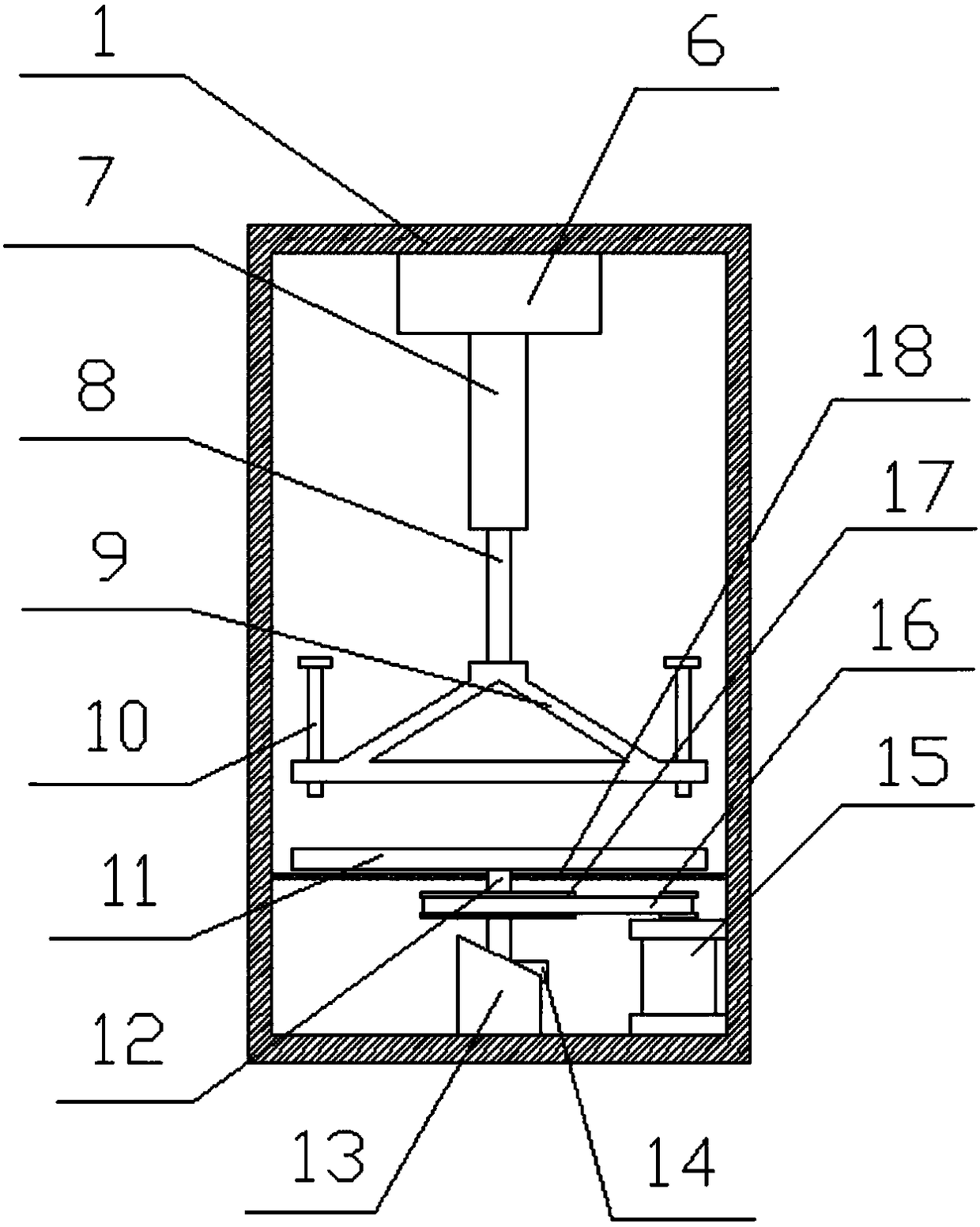
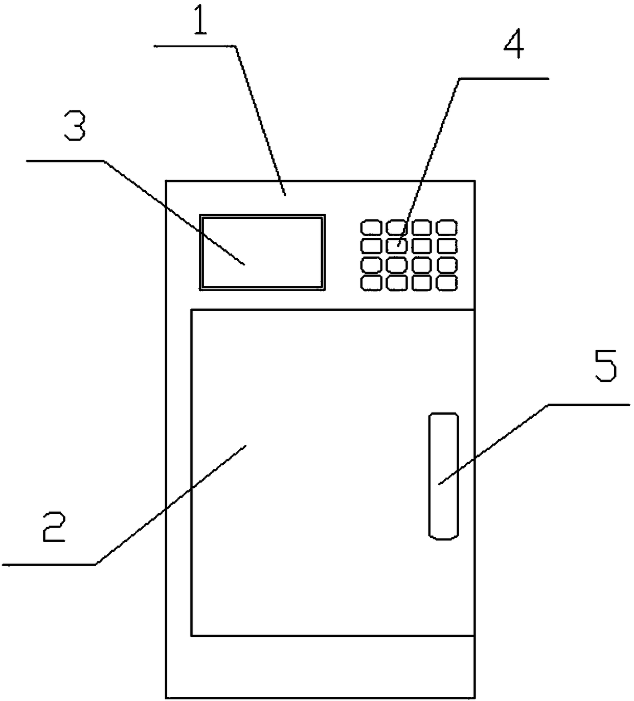
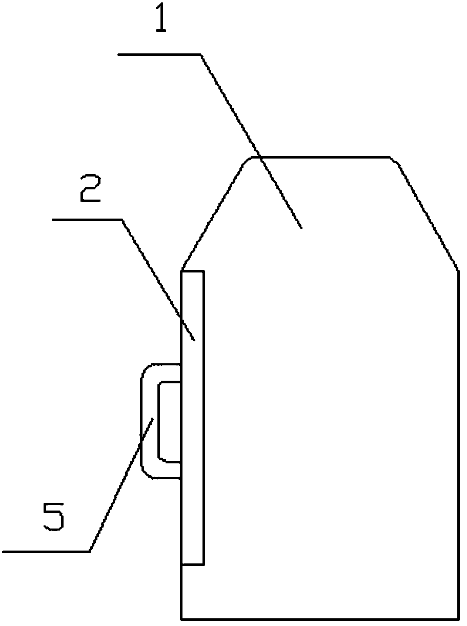
[0021] Such as Figure 2 to Figure 5 As shown, a liquid medicine shaking device includes a housing 1. The housing 1 includes an oscillating mechanism and a pressing mechanism. The oscillating mechanism is provided on the bottom surface of the housing 1, and includes a turntable 11, a rotating rod 12, and a motor. 15 and a limiting column 13, the rotating rod 12 is fixedly connected to the bottom of the rotating disk 11, a pulley 17 is fixed on the rotating rod 12, and the pulley 17 is connected to the motor 15 through a belt 16. The limiting column 13 is a hollow cylinder, and its top end is an inclined surface. The rotating rod 12 is sleeved inside the limiting column 13, and the rotating rod 12 is provided with a limiting block that is clamped on the side wall of the limiting column 13 14. The motor 15 drives the turntable 11 to rotate through the belt 16. During the rotation, the limit block 14 slides on the outer wall of the limit column 13. Because the out...

Example Embodiment

[0026] Example 2

[0027] Such as Figure 1 to Figure 4 As shown, a liquid medicine shaking device includes a housing 1. The housing 1 includes an oscillating mechanism and a pressing mechanism. The oscillating mechanism is provided on the bottom surface of the housing 1, and includes a turntable 11, a rotating rod 12, and a motor. 15 and a limiting column 13, the rotating rod 12 is fixedly connected to the bottom of the rotating disk 11, a pulley 17 is fixed on the rotating rod 12, and the pulley 17 is connected to the motor 15 through a belt 16. The limiting column 13 is a hollow cylinder, and its top end is an inclined surface. The rotating rod 12 is sleeved inside the limiting column 13, and the rotating rod 12 is provided with a limiting block that is clamped on the side wall of the limiting column 13 14. The motor 15 drives the turntable 11 to rotate through the belt 16. During the rotation, the limit block 14 slides on the outer wall of the limit column 13. Because the ou...


PUM


Abstract

The invention discloses a medicinal liquid shaking device, and relates to the field of medicine production. The medicinal liquid shaking device comprises a casing, wherein an oscillating mechanism anda pressing mechanism are arranged inside the casing; the oscillating mechanism is arranged on the inner bottom surface of the casing, and comprises a turnplate, a rotating rod, a motor and a limitingcolumn; the rotating rod is fixedly connected to the bottom of the turnplate; a belt pulley is fixedly arranged on the rotating rod; the belt pulley is connected with the motor through a belt; the limiting column is a hollow cylinder, and the top end thereof is an inclined plane; the rotating rod is sleeved with the limiting column; a limiting block connected to the side wall of the limiting column in a clamping manner is arranged on the rotating rod; the pressing mechanism is arranged on the inner top surface of the casing, and comprises a connecting platform, a hollow tube, a telescopic rodand a triangular rack. The medicinal liquid shaking device can shake medicinal liquid up and down while rotation of the medicinal liquid is achieved, so that mixing of the medicinal liquid is more uniform and higher in efficiency.

Description

technical field [0001] The invention relates to the field of medicine production, in particular to a medicine liquid shaking device. Background technique: [0002] When doing experiments, it is usually necessary to mix the powder and liquid to test the properties of the drug. If the liquid is not shaken to fully mix the powder and liquid, it will lead to an error in the structure of the test, and it is not ideal to shake a large amount of liquid by manpower. , so in order to accelerate the rapid mixing of powder and liquid, a drug solution shaking device suitable for use in the laboratory is needed. [0003] For example, the application number is CN201720296101.7, which discloses a medicinal liquid shaker assembly and a liquid dispensing machine containing it. The medicinal liquid shaker assembly includes: a medicine bottle clamp, on which at least one Shake the medicine bottle of the medicine liquid, the medicine bottle clamp is detachably connected with the medicine bottl...

Claims


Application Information

Patent Timeline
IPC IPC(8): B01F11/00B01F15/00
CPCB01F31/201B01F31/25B01F35/221422B01F2101/23
Inventor 许震
Owner WUHU NOKAN BIOTECH
Why Eureka
Try Eureka