Adaptive stamping die positioning structure

A stamping die and positioning structure technology, applied in the field of stamping dies, can solve the problems of low yield rate of stamping parts, easy to produce deviations, stamping die positioning requires human intervention, etc., to achieve the effect of improving production accuracy and automation level

Active Publication Date: 2018-09-21
广东顺德慎业丰五金电器有限公司
View PDF6 Cites 0 Cited by
  • Summary
  • Abstract
  • Description
  • Claims
  • Application Information

AI Technical Summary

Problems solved by technology

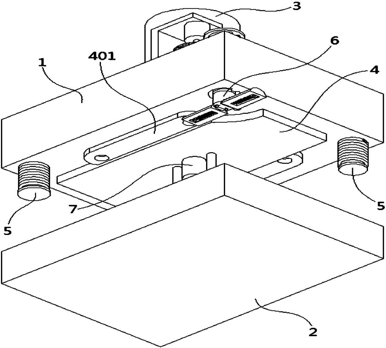
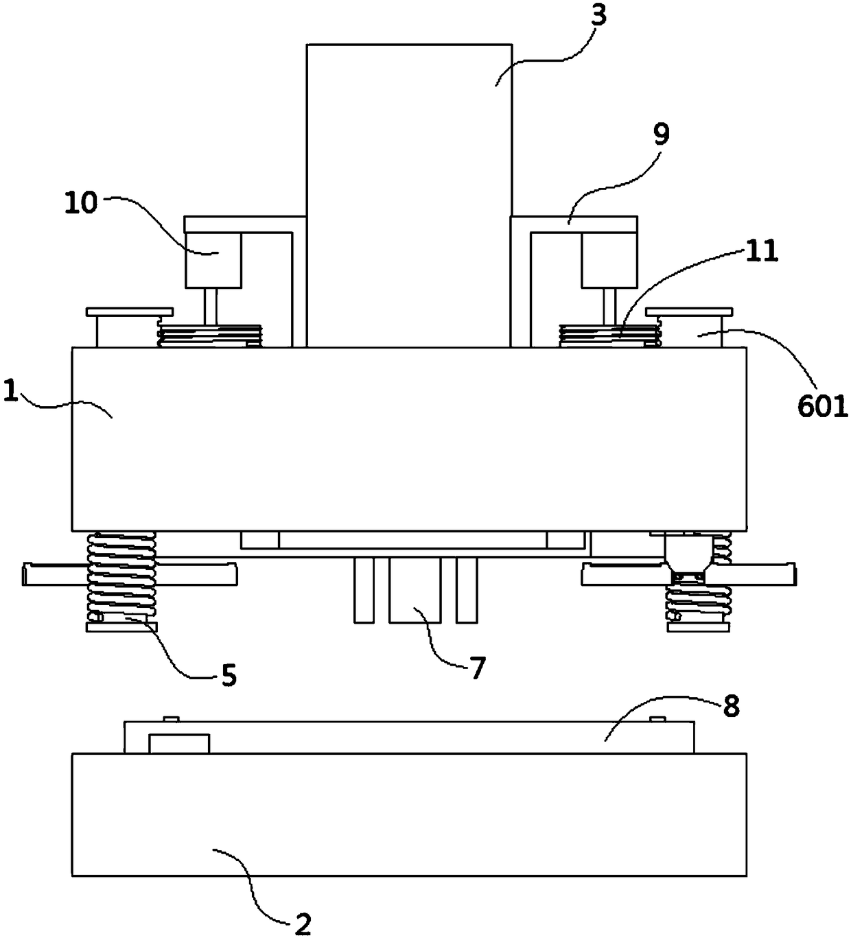
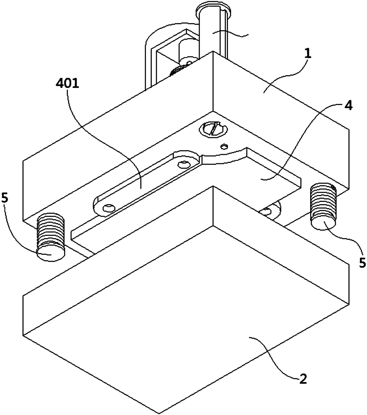
[0004] Aiming at the deficiencies of the prior art, the present invention provides an adaptive stamping die positioning structure. Through the positioning device, the positioning work of the upper mold base and the lower mold base is realized without contact, and the physical contact parts are solved. The problem of wear and tear is prone to deviation, and the scanning structure of the infrared sensor can further improve the positioning accuracy of the stamping die, and solve the problem of low yield rate of stamping parts; through the cooperation of the guide column and the storage block, the positioning device can be realized automatically when it is not in use. Storage, which solves the problem of manpower intervention in the positioning of stamping dies

Method used


Image

  • Adaptive stamping die positioning structure
  • Adaptive stamping die positioning structure
  • Adaptive stamping die positioning structure

Examples


Embodiment Construction

[0035] The following will clearly and completely describe the technical solutions in the embodiments of the present invention with reference to the accompanying drawings in the embodiments of the present invention. Obviously, the described embodiments are only some, not all, embodiments of the present invention. Based on the embodiments of the present invention, all other embodiments obtained by persons of ordinary skill in the art without creative efforts fall within the protection scope of the present invention.

[0036] In describing the present invention, it is to be understood that the terms "opening", "upper", "lower", "thickness", "top", "middle", "length", "inner", "surrounding" etc. Indicating orientation or positional relationship is only for the convenience of describing the present invention and simplifying the description, and does not indicate or imply that the components or elements referred to must have a specific orientation, be constructed and operated in a sp...


PUM

PropertyMeasurementUnit
lengthaaaaaaaaaa

Abstract

The invention discloses an adaptive stamping die positioning structure and relates to the technical field of stamping dies. The adaptive stamping die positioning structure comprises an upper die seatand a lower die seat; one surface of the upper die seat is fixedly connected with a die shank; the other surface of the upper die seat is fixedly connected with a convex die and provided with a plurality of unloading rods, a plurality of positioning devices and a lifting pin; one end of the lifting pin penetrates through the convex die and extends out of the convex die; one surface of the lower die seat is fixedly connected with a concave die; one surface of the upper die seat is fixedly connected with a plurality of fixing supports; one surface of each fixing support is fixedly connected witha drive device; one end of an output shaft of each drive device is fixedly connected with a threaded plate; one surface of each threaded plate is rotationally connected with the upper die seat; and the circumferential side face of each threaded plate is in threaded connection with the corresponding positioning device. By means of the positioning devices, the upper die seat and the lower die seatcan be automatically positioned without making contact, and thus the adaptive stamping die positioning structure has the advantage that the production precision is further improved.

Description

technical field [0001] The invention relates to the technical field of stamping dies, in particular to an adaptive stamping die positioning structure. Background technique [0002] Stamping die is a special process equipment for processing materials into parts in cold stamping processing, called cold stamping die. Stamping is a pressure processing method that uses a mold installed on a press to apply pressure to the material at room temperature to cause separation or plastic deformation to obtain the required parts. [0003] At present, stamping dies on the market use guide posts and positioning pins to realize the positioning function during die stamping, but the physical contact and friction between the structures during positioning is likely to cause die wear, and long-term use of stamping dies will lead to a decrease in processing accuracy. The yield rate of production is reduced. Contents of the invention [0004] Aiming at the deficiencies of the prior art, the pre...

Claims


Application Information

Patent Timeline
Patent Type & Authority Applications(China)
IPC IPC(8): B21D37/10B21D37/12B21C51/00
CPCB21C51/00B21D37/10B21D37/12
Inventor 赵战锋
Owner 广东顺德慎业丰五金电器有限公司
Why Eureka
Try Eureka