A surface texture device and texture method based on ultrasonic vibration shock
A technology of ultrasonic vibration and surface texture, which is applied in the fields of automatic lathes/semi-automatic lathes, manufacturing tools, design optimization/simulation, etc., which can solve the difficulty of flexible control of texture size and distribution, joint damage to the workpiece surface, and low processing efficiency etc. to achieve good texture diversity, low cutting heat, and easy disassembly and assembly
- Summary
- Abstract
- Description
- Claims
- Application Information
AI Technical Summary
Problems solved by technology
Method used
Image
Examples
Embodiment 1
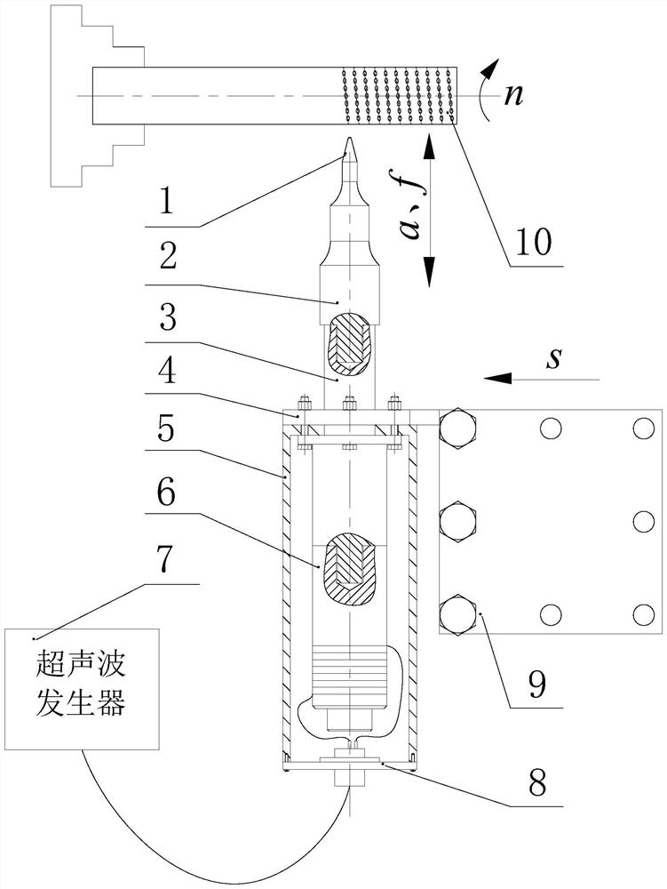
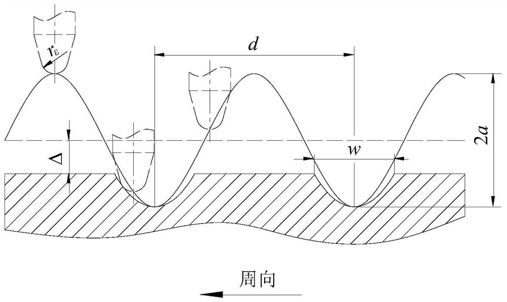
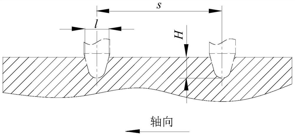
[0092] The present invention uses a method for texturing a surface texturing device based on ultrasonic vibration impact. When texturing the outer surface of a rotating body, such as figure 2 and image 3 As shown, the workpiece 10 is rotated by the spindle motor of the lathe, and the ultrasonic vibration system moves longitudinally along with the tool holder 9 in a direction parallel to the centerline of the spindle, and the ultrasonic generator 7 converts alternating current into a sinusoidal electrical oscillation signal of ultrasonic frequency And transmit it to the transducer 6 through the wire, the transducer 6 converts the electrical oscillation signal into ultrasonic frequency mechanical vibration, and then the horn 3 amplifies the ultrasonic frequency mechanical vibration of the transducer 6 and transmits it to the cutter bar 2, The cutter bar 2 drives the cutter head 1 to perform reciprocating ultrasonic mechanical vibration in the direction perpendicular to the sur...
Embodiment 2
[0102] The present invention uses a method for texturing a surface texturing device based on ultrasonic vibration impact. When texturing the end face of a rotating body, such as Figure 5As shown, the workpiece 10 is rotated by the spindle motor of the lathe, and the ultrasonic vibration system moves laterally with the tool holder 9 in a direction perpendicular to the centerline of the spindle, and the ultrasonic generator 7 converts alternating current into a sinusoidal electrical oscillation signal of ultrasonic frequency And transmit it to the transducer 6 through the wire, the transducer 6 converts the electrical oscillation signal into ultrasonic frequency mechanical vibration, and then the horn 3 amplifies the ultrasonic frequency mechanical vibration of the transducer 6 and transmits it to the cutter bar 2, The cutter bar 2 drives the cutter head 1 to perform reciprocating ultrasonic mechanical vibration in the direction perpendicular to the end face of the rotary body, ...
PUM
 Abstract
Description
Claims
Application Information
 - R&D
- Intellectual Property
- Life Sciences
- Materials
- Tech Scout
- Unparalleled Data Quality
- Higher Quality Content
- 60% Fewer Hallucinations
Browse by: Latest US Patents, China's latest patents, Technical Efficacy Thesaurus, Application Domain, Technology Topic, Popular Technical Reports.
© 2025 PatSnap. All rights reserved.Legal|Privacy policy|Modern Slavery Act Transparency Statement|Sitemap|About US| Contact US: help@patsnap.com


