Multi-compartment box nailing machine and nailing method

A nailing machine and box technology, applied in the field of machinery, can solve the problems of time-consuming, labor-intensive, low efficiency, etc., and achieve the effect of easy operation of the equipment, fast nailing, and improved production efficiency

Pending Publication Date: 2018-09-21
SHANGHAI BAOYE ELECTROMECHANICAL TECH CO LTD
View PDF5 Cites 2 Cited by
  • Summary
  • Abstract
  • Description
  • Claims
  • Application Information

AI Technical Summary

Problems solved by technology

The bottom plate of the traditional "non-standard reinforced insulation box" is connected by manual self-tapping screws, which is inefficient and time-consuming. Therefore, we propose a multi-compartment box nailing machine and nailing method.

Method used


Image

  • Multi-compartment box nailing machine and nailing method
  • Multi-compartment box nailing machine and nailing method
  • Multi-compartment box nailing machine and nailing method

Examples


Embodiment 1

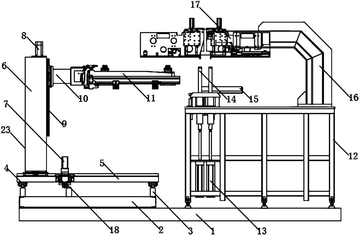
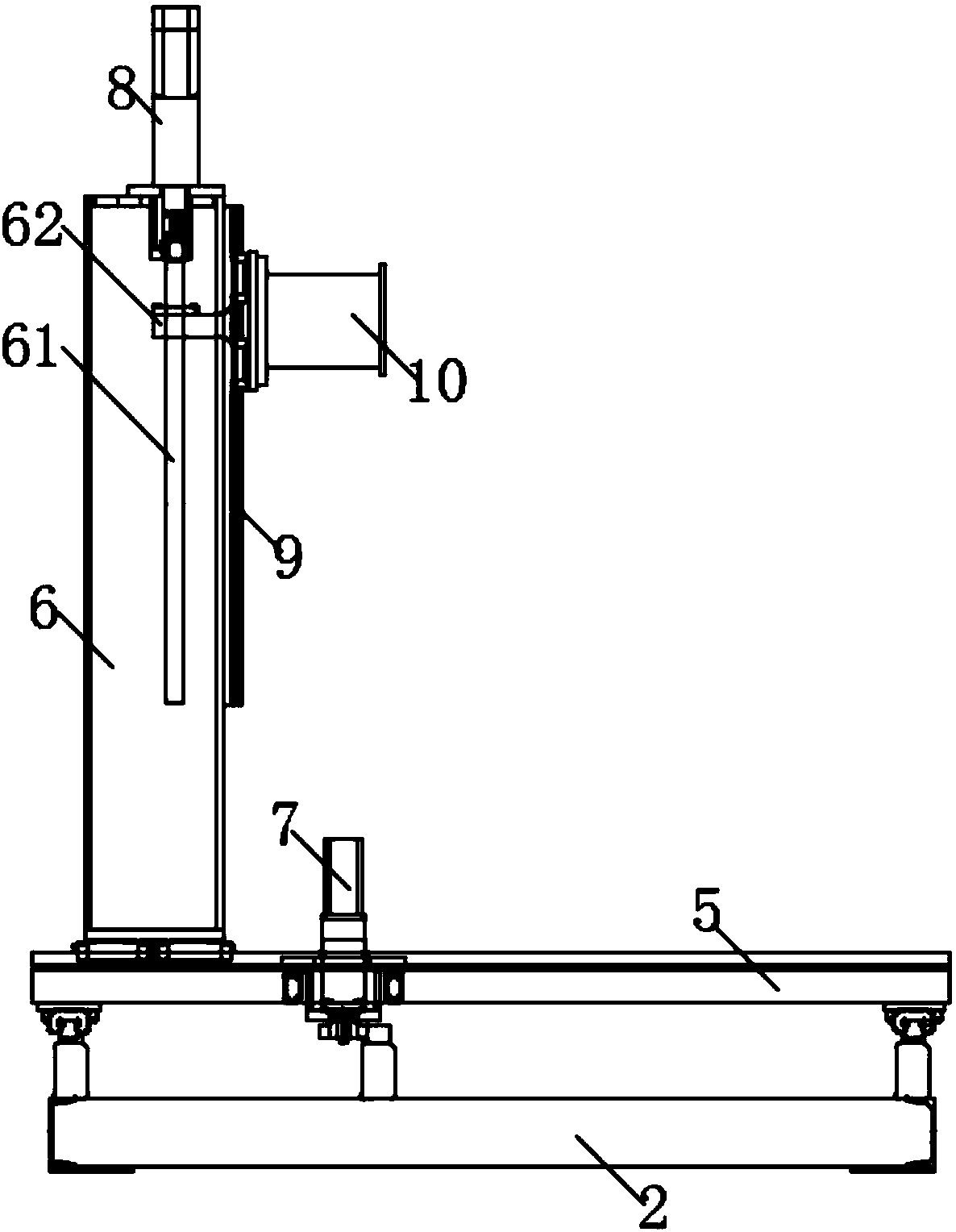
[0027] see Figure 1-4 , the present invention provides a technical solution: a multi-compartment box nailing machine, including a bottom plate 1, a first support plate 2 is provided on the left side of the upper end of the bottom plate 1, and the first support plate 2 is used to support the second support Plate 5, the upper end of the first support plate 2 is provided with a conveying unit 23, the upper end of the first support plate 2 is fixed on the left and right sides of the first sliding guide rail 3, and the upper end of the first sliding guide rail 3 is provided with a second A guide rail slider 4, the upper end of the first guide rail slider 4 is fixedly connected to the left and right sides of the lower end of the second support plate 5, a rack 18 is provided in the middle of the upper end of the first support plate 2, and the first The rack 18 is in mesh with the first gear, and the first gear is sleeved on the lower end shaft of the first motor 7, and the first mot...

Embodiment 2

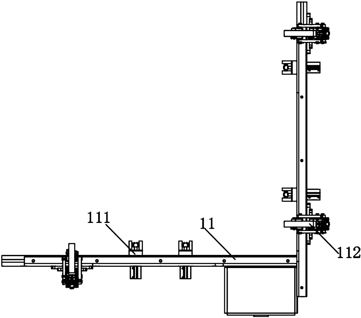
[0033] see image 3 and 5 The present invention provides a technical solution: the conveying unit 23 includes a third sliding track 19, a support plate 20, a fourth motor 21 and a manipulator 22, and the four corners of the upper end of the first supporting plate 2 are fixedly connected with the third sliding track 19, The upper end of the third sliding track 19 is connected with a support plate 20 through a pulley, the right end of the support plate 20 is fixedly connected with a fourth motor 21, and the lower end of the fourth motor 21 is connected to the third sliding track 19 through a transmission wheel. The upper end of the support plate 20 is fixedly connected with the manipulator 22 , and the right end of the manipulator 22 is fixedly connected with the clamping arm 11 .

[0034] A nailing method for a multi-compartment box nailing machine is characterized in that it comprises the following steps:

[0035] 1), place the material that needs to be nailed on the clampin...


PUM


Abstract

The invention discloses a multi-compartment box nailing machine and a nailing method. A first supporting plate is arranged on the left side of the upper end of a bottom plate, a conveying unit is arranged at the upper end of the first supporting plate, the right end of a connecting column is fixedly connected with a clamping arm, the clamping arm comprises a clamping block and a compression rod, asupport is placed on the right side of the upper end of the bottom plate, the left lower portion of the support is fixedly connected with a cylinder, the upper end of a cylinder transmission rod is connected with an ejector rod through a buffer rod, and a roller conveyor is arranged on the rear side of the left end of the support. According to the multi-compartment box nailing machine, an ejectorrod can buffer impact force of a nail gun, so that the nail gun is more stable in nailing. By the aid of an integrated structure, production efficiency is improved, labor cost is saved, and the multi-compartment box nailing machine has low maintenance cost.

Description

technical field [0001] The invention relates to the field of mechanical technology, in particular to a multi-compartment box nailing machine and a nailing method. Background technique [0002] For a long time, the bottom plate connection of the traditional "non-standard reinforced insulation box" needs to use templates to realize the precise positioning of the screw connection position to ensure the accuracy of the screw connection position. The bottom plate of the traditional "non-standard reinforced insulation box" is connected by manual self-tapping screws, which is inefficient and time-consuming. Therefore, we propose a multi-compartment box nailing machine and nailing method. Contents of the invention [0003] The object of the present invention is to provide a multi-compartment box nailing machine and a nailing method to solve the problems raised in the above-mentioned background technology. [0004] In order to achieve the above object, the present invention provid...

Claims


Application Information

Patent Timeline
Patent Type & Authority Applications(China)
IPC IPC(8): B23P19/06
CPCB23P19/06
Inventor 周春立蒋知峰
Owner SHANGHAI BAOYE ELECTROMECHANICAL TECH CO LTD
Why Eureka
Try Eureka