Energy storage bank pool built in underground mine and construction method thereof

A storage group and storage technology, applied in the field of energy storage group and its construction

Active Publication Date: 2018-09-21
XIAN UNIV OF SCI & TECH
View PDF7 Cites 1 Cited by
  • Summary
  • Abstract
  • Description
  • Claims
  • Application Information

AI Technical Summary

Problems solved by technology

But, in the prior art, there is also a lack of such an energy storage group built under the mine shaft, and there is no method for building such an energy storage group, and wh

Method used


Image

  • Energy storage bank pool built in underground mine and construction method thereof
  • Energy storage bank pool built in underground mine and construction method thereof
  • Energy storage bank pool built in underground mine and construction method thereof

Examples


Embodiment 1

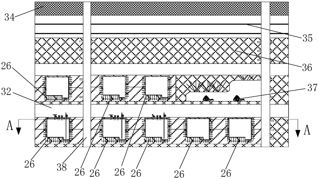
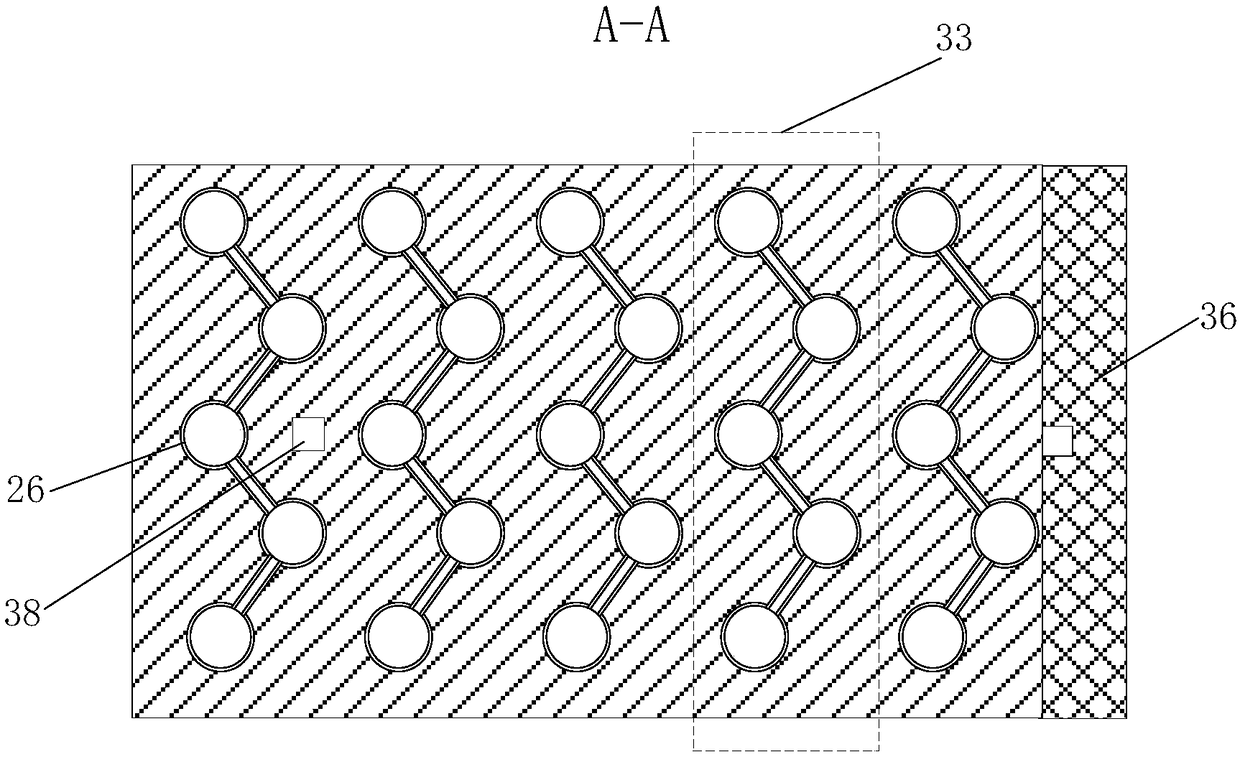
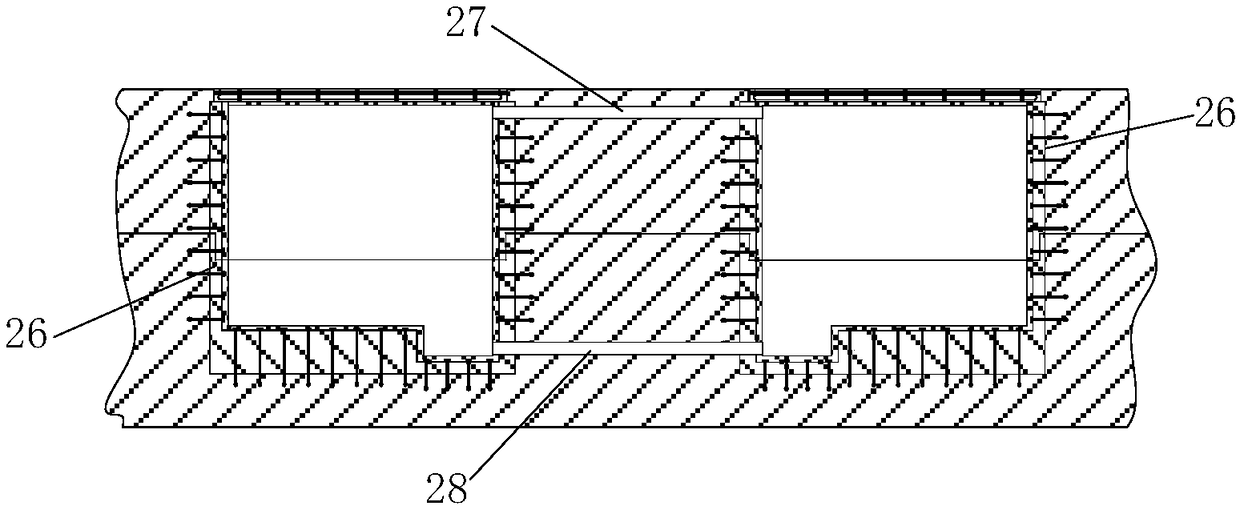
[0124] Such as Figure 1 to Figure 5 As shown, the energy storage group built in the underground of the mine in this embodiment includes a plurality of energy storage groups 33, and each energy storage group 33 includes a plurality of energy storages 26, and each energy storage group 33 The tops of two adjacent energy storage banks 26 are connected by upper communication pipes 27, and the lower parts of two adjacent energy storage stores 26 in each energy storage bank group 33 are connected by lower communication pipelines 28, and in each energy storage bank group 33 Three adjacent energy storages 26 are arranged in an equilateral triangle. The energy storages 26 include a storage body, and the storage body of the energy storage 26 located directly below the transportation roadway 32 is provided with an energy transmission pipeline assembly.

[0125] In this embodiment, the top of the storage body of the energy storage 26 located directly below the transportation roadway 32 is...

Embodiment 2

[0216] In this embodiment, one pipeline is used for energy input and output of the energy storage.

[0217] Such as Figure 6 As shown, the energy storage group built in the underground of the mine in this embodiment is different from Embodiment 1 in that: the energy transmission pipeline assembly includes an energy input and output pipeline 30 and a set The energy input and output control valve 31 on the energy input and output pipeline 30 extends into the collection pool 1-4. All the other structures are the same as in Example 1.

[0218] The construction method of the energy storage group built in the underground of the mine in this embodiment is different from Embodiment 1 in that:

[0219] Step 17. When prefabricating the reinforced roof 3 for fixed connection to the energy storage 26 directly below the transportation roadway 32, set the reserved hole 29 for energy input and output pipelines on the reinforced roof 3;

[0220] Step 1722: Pour the anti-seepage material i...


PUM


Abstract

The invention discloses an energy storage bank pool built in the underground mine which comprises a plurality of energy storage bank groups, and each energy storage bank group comprises a plurality ofenergy storage banks. The upper parts of every two adjacent energy storage banks in each energy storage bank group are connected with an upper communicating pipe, and the lower parts of every two adjacent energy storage banks in each energy storage bank group are connected with a lower communicating pipe. Every three adjacent energy storage banks in each energy storage bank group are laid out inan equilateral triangle distribution. The energy storage bank comprises a mainbody, and on the mainbody which is located right under the transportation tunnel, energy delivery pipeline components arearranged. The invention also discloses a method for constructing an energy storage bank pool built in underground mine. The method features novel and reasonable design, sound stability and feasibility, and the energy storage banks built according to the method are of stable structure, high strength, good sealing performance, good anti-seepage performance and high energy storage safety, which willlead to reasonable utilization of the depleted mine and pave the way for exploration of the energy storage bank with a high value in popularization and application.

Description

technical field [0001] The invention belongs to the technical field of mining and energy storage, and in particular relates to an energy storage group built under a mine and a construction method thereof. Background technique [0002] In the mining process of metal mineral resources, the goaf has the characteristics of huge spatial scale, complex geological environment and serious safety hazards. At present, the treatment measures for gobs in metal mines mainly include: treatment of surrounding rock collapse, filling treatment, permanent pillar treatment, sealing treatment and other methods. Permanently leaving ore pillars is not conducive to efficient mining of resources, and the treatment of collapsed surrounding rocks is not conducive to the protection of the surface environment, and the closed treatment has great safety hazards. Filling is an effective technical method to achieve safe, clean and efficient mining of ore deposits, and it plays a dual role in protecting th...

Claims


Application Information

Patent Timeline
IPC IPC(8): E21F17/16
CPCE21F17/16
Inventor 张波刘浪王美张小艳王湃陈柳秦学斌景宏君王燕邱华富孙伟博方治余辛杰
Owner XIAN UNIV OF SCI & TECH
Why Eureka
Try Eureka