Bidirectional hydraulic lock

A two-way hydraulic lock and one-way valve technology, applied in the direction of fluid pressure actuators, valve details, engine components, etc., can solve problems such as equipment abnormalities, large propulsion strokes, and vibrations, and achieve the goal of improving service life and stability Effect

Pending Publication Date: 2018-09-21
宁波善研液压有限公司
View PDF9 Cites 4 Cited by
  • Summary
  • Abstract
  • Description
  • Claims
  • Application Information

AI Technical Summary

Problems solved by technology

[0004] This two-way hydraulic lock also has certain shortcomings. For example, after the hydraulic oil enters from the oil inlet of the two-way hydraulic lock, it directly acts on the spool and piston in the valve cavity, which will cause the hydraulic lock to open or close. , the hydraulic oil entering the valve cavity at a high speed forms a severe impact on the valve core and the piston, causing jitter or vibration, which seriously affects the normal operation of the lifting equipment; The push rod on the side always acts on the spool in the valve cavity. However, when the hydraulic oil enters the valve cavity at high speed, the internal pressure of the valve cavity is relatively large, and the push stroke of the push rod to the spool also becomes large, which is prone to push The rod is deformed or even broken, resulting in abnormal equipment and seriously shortening the service life of the hydraulic lock

Method used


Image

  • Bidirectional hydraulic lock
  • Bidirectional hydraulic lock
  • Bidirectional hydraulic lock

Examples


Embodiment Construction

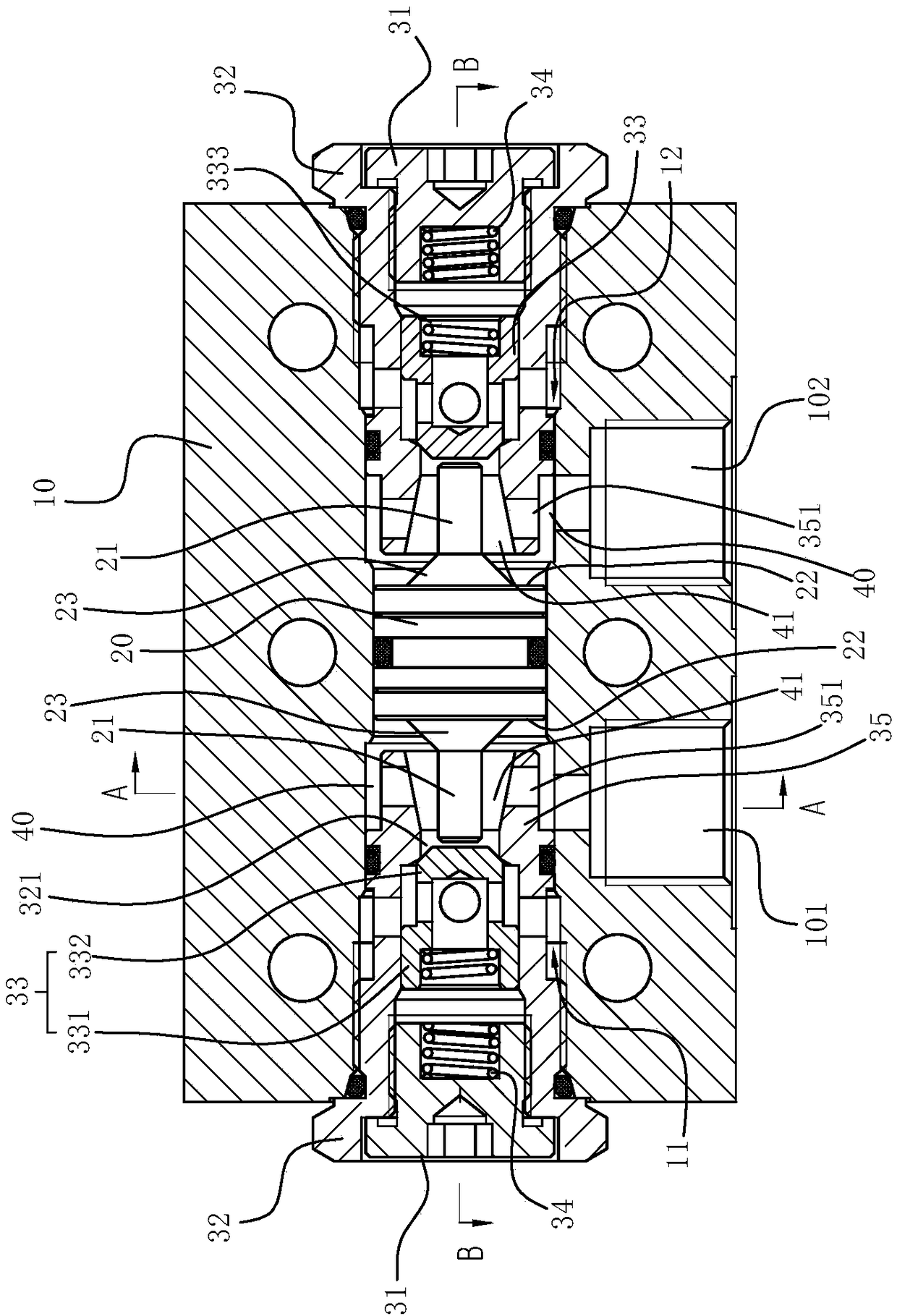
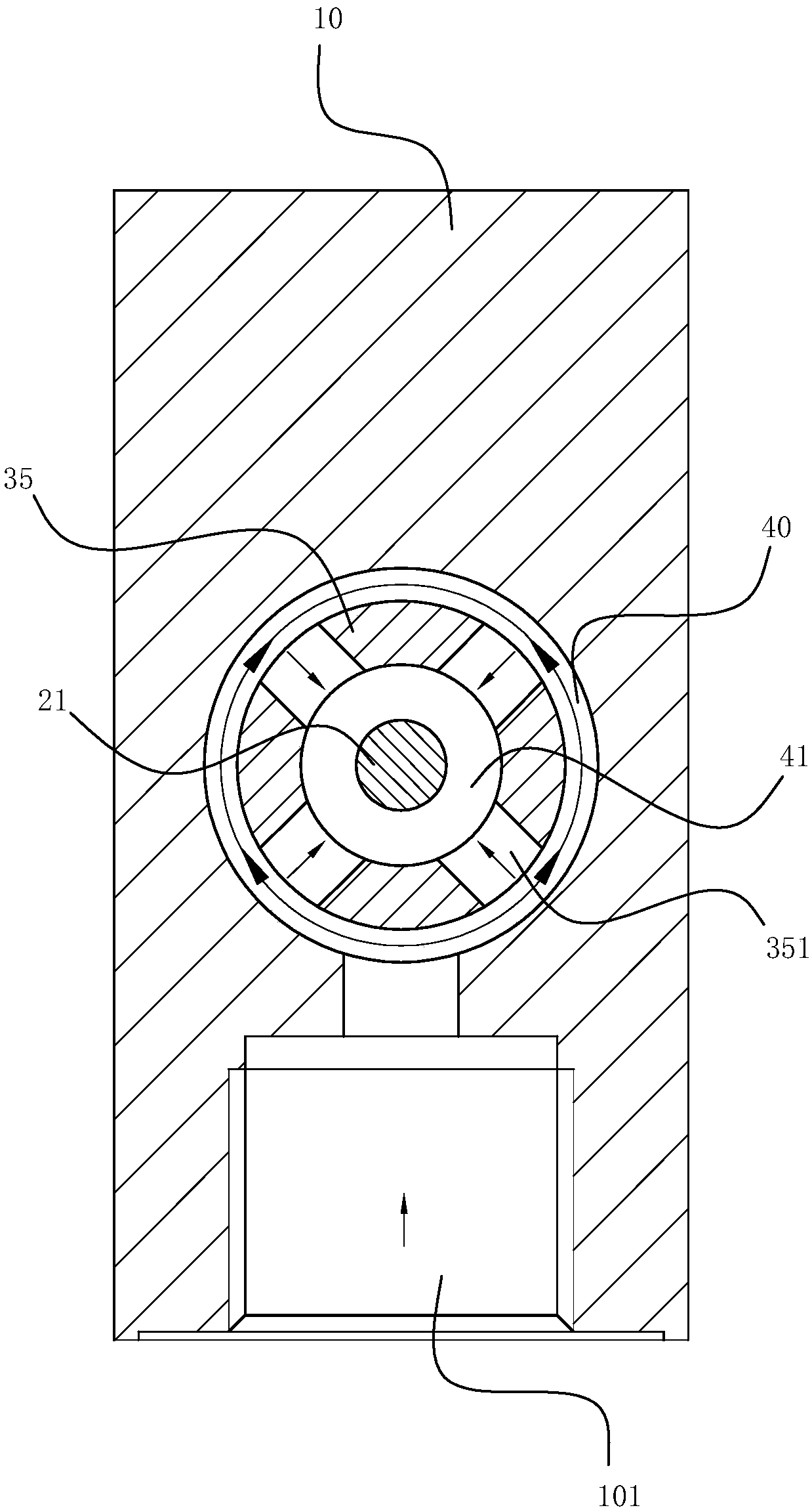
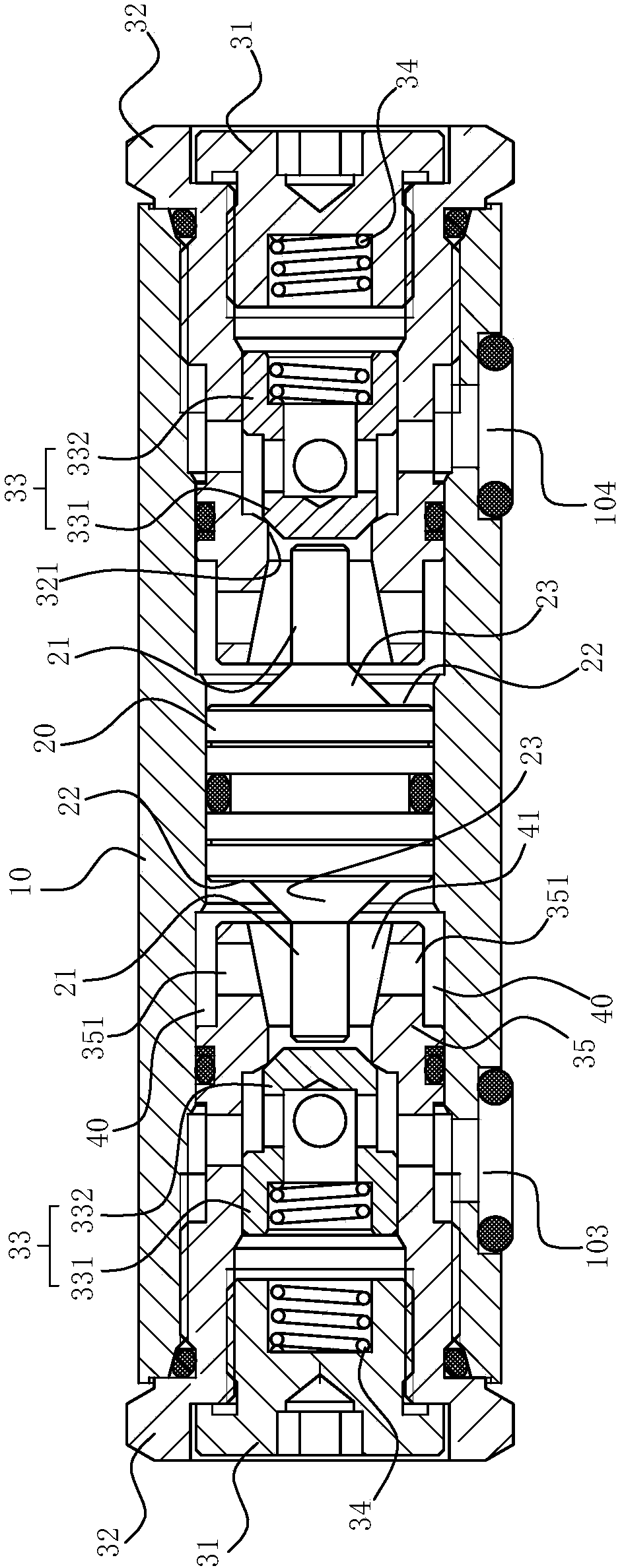
[0022] The present invention will be further described in detail below in conjunction with the accompanying drawings and embodiments.

[0023] Such as Figure 1 ~ Figure 3 As shown, the two-way hydraulic lock includes a valve body 10, a plunger 20 and a one-way valve, wherein the valve body 10 has a coaxial first valve chamber 11 and a second valve chamber 12, and the plunger 20 is slidably arranged on the valve body 10, and isolate the first valve chamber 11 from the second valve chamber 12, there are two check valves, which are respectively located in the first valve chamber 11 and the second valve chamber 12, refer to Figure 4 , in this embodiment, the one-way valve includes an end cover 31, a valve sleeve 32, a valve core 33, and an elastic member 34 disposed in the inner cavity of the valve sleeve 32 and held between the end cover 31 and the valve core 33, Wherein, the valve sleeve 32 has a valve port 321, the valve core 33 can be movably arranged in the inner cavity of...


PUM


Abstract

The invention relates to a bidirectional hydraulic lock. An annular extension part which can extend from the position of a valve hole to a plunger and prop against a corresponding side of the prop tolimit the movement of the plunger is formed on the peripheral wall of the valve hole of a valve sleeve of a one-way valve of the bidirectional hydraulic lock, and the extension length of the annular extension part is smaller than that of a plunger rod, so that the plunger rod can penetrate through the annular extension part to drive a valve element; and a first gap for hydraulic oil to flow is formed between the outer wall of the annular extension part and the inner wall of a valve body, and a second gap for hydraulic oil to flow is formed between the inner wall of the annular extension part and the outer wall of the plunger rod, and a plurality of throttling channels for hydraulic oil to flow between the first gap and the second gap is further formed in the annular extension part. According to the bidirectional hydraulic lock, the propelling stroke of the plunger can be limited by the annular extension part, so that the situation that the plunger rod is deformed or broken due to an overlarge force can be avoided, the service life of the hydraulic lock is prolonged, and the bidirectional hydraulic lock is relatively smooth and steady in the working process.

Description

technical field [0001] The invention relates to a hydraulic control device, in particular to a two-way hydraulic lock. Background technique [0002] Hydraulic lock, a device that plays a locking role in the oil circuit of the hydraulic cylinder, it can reliably stop the heavy object and the actuator at any position required for work, and play a role of locking and maintaining pressure to ensure the safe and reliable operation of the main engine . [0003] For example, the Chinese invention patent whose application number is CN201410118740.5 (publication number is CN104948532A) discloses "A Two-way Hydraulic Lock", which includes a valve body, a left spool, a right spool, two push rods and a The piston is provided with two valve chambers in the valve body, the left valve core or the right valve core is arranged in the valve chamber, and the piston is arranged in the middle of the valve body. The two valve chambers are respectively connected to an oil inlet and an oil outlet...

Claims


Application Information

Patent Timeline
Patent Type & Authority Applications(China)
IPC IPC(8): F15B13/01F16K47/08
CPCF15B13/01F16K47/08
Inventor 王江山王江海黄昆许强
Owner 宁波善研液压有限公司
Why Eureka
Try Eureka