Special measuring device for building design

A measurement device and architectural design technology, applied in the direction of measurement devices, mechanical measurement devices, and mechanical devices, can solve the problems of high labor intensity, loss of economic benefits, low efficiency, etc., and achieve low labor intensity for workers, convenient and accurate measurement, Ease of use

Inactive Publication Date: 2018-09-21
李明
View PDF5 Cites 9 Cited by
  • Summary
  • Abstract
  • Description
  • Claims
  • Application Information

AI Technical Summary

Problems solved by technology

[0003] In view of the above situation, in order to overcome the defects of the prior art, the present invention provides a special measurement device for architectural design, which effectively solves the problems of the existing manual measurement, such as large error in taking long time, high labor intensity, low efficiency, loss of economic benefits, etc. It has the characteristics of reducing raw material consumption, saving manpower, saving costs, etc., thus improving economic benefits

Method used


Image

  • Special measuring device for building design
  • Special measuring device for building design
  • Special measuring device for building design

Examples


Embodiment 1

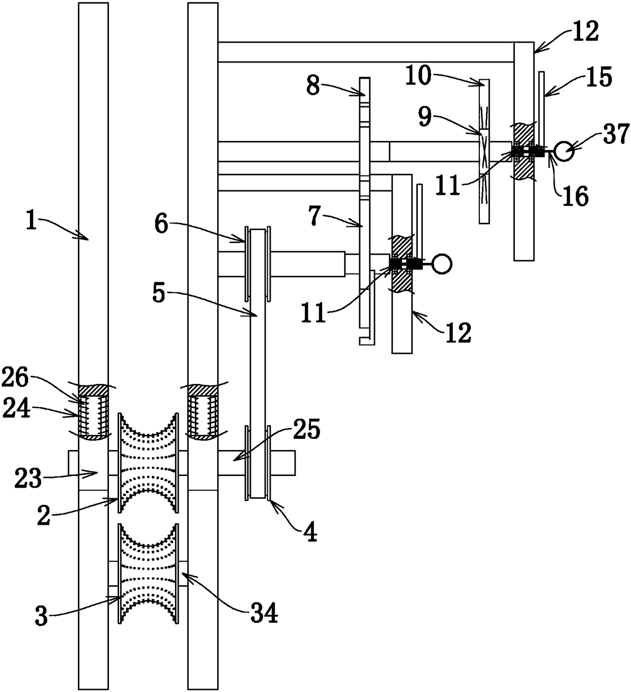
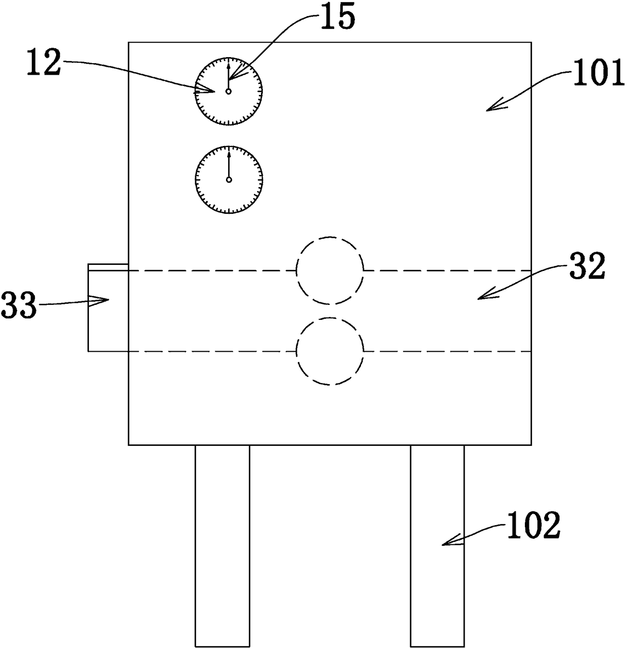
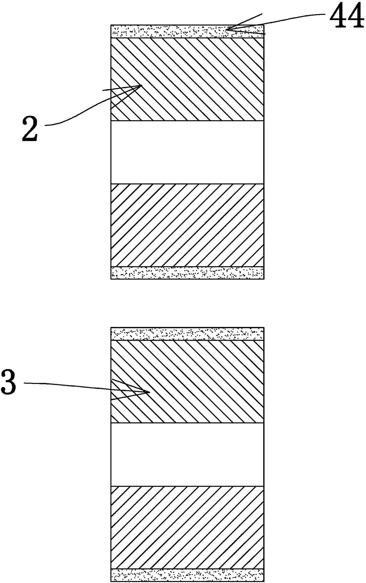
[0037] Embodiment 1 includes a frame 1, the frame 1 includes a casing 101 and legs 102 arranged in a rectangular arrangement at the bottom of the casing 101, the frame 1 is provided with a first wheel 2, the first A second runner 3 is rotatably connected to the frame 1 below the runner 2, and steel strands can pass between the first runner 2 and the second runner 3. The first rotation 2 and the second runner 3 They are all arranged in the housing 101, and there is an elastic mechanism between the first runner 2 and the frame 1 so that the first runner 2 can move up and down and has a downward pressure. During use, the steel strand Enter from the entrance of the housing 101, and then enter between the first runner 2 and the second runner 3, the interval between the first runner 2 and the second runner 3 in the initial state is less than the diameter of the steel strand, And because the surface of the first runner 2 and the second runner 3 facing the entrance is an arc surface, ...

Embodiment 2

[0038] Embodiment 2, on the basis of Embodiment 1, the two ends of the first runner 2 are rotatably connected with a bearing seat 23 via a first rotating shaft 25, and the bearing seat 23 is vertically slidably connected to the frame 1. The upper end of the bearing seat 23 is connected with the second compression spring 24 whose other end is connected on the frame 1, constituting an elastic force device. Specifically, a first rotating shaft 25 is fixedly connected to both ends of the first rotating wheel 2, and a bearing housing 23 is rotationally connected to both ends of the first rotating shaft 25, and a plurality of sliding rods 26 are vertically slidingly connected in the bearing housing 23, and the sliding rods 26 The upper and lower ends of the upper and lower ends are respectively fixed on the frame 1, and the two ends of the slide bar 26 are respectively fixed on the second stage clip 24 at the upper end of the bearing on the frame 1. When the steel strand continuousl...

Embodiment 3

[0039] Embodiment 3, on the basis of Embodiment 1, the tensioning device of the belt 5 includes a sleeve 27 fixed on the frame 1, and the sleeve 27 is axially slidably connected with a movable rod 28, and the movable rod 28 free ends are connected with a base bar 29 perpendicular thereto, and the front and rear ends of the base bar 29 are respectively connected with vertical support bars 30, and also include a tension pulley 31 connected to the belt 5, the tension pulley The two ends of 31 are rotatably connected to two supporting rods 30 respectively, and a tension spring 44 sleeved on the movable rod 28 is connected between the sleeve 27 and the base rod 29 . The belt 5 tensioning device makes when the first pulley 4 follows the first runner 2 and jumps up and down, the belt 5 between the first pulley 4 and the second belt 6 is always stretched, and will not slip, which improves the measurement precision.


PUM


Abstract

The invention provides a special measuring device for building design. The problems of large error, high labor intensity, low efficiency, economic benefit loss and the like of the existing manual length measurement are effectively solved. The device has the characteristics of raw material consumption reducing, manpower saving, cost saving and the like. The economic efficiency is improved. According to the invention, the length of a steel strand is measured through a mechanical structure; electric energy is not used; the device is conveniently used in the measurement process of the steel strand; the device has the advantages of convenient and accurate measurement and low worker labor intensity, and is suitable for the measurement of batch steel strands; the length of the steel strand is determined on a dial according to needs; and after the steel strand reaches a length, a holding device automatically holds the steel strand tightly to automatically acquire the steel strand of required length.

Description

technical field [0001] The invention relates to the field of architectural design, in particular to a special measuring device for architectural design. Background technique [0002] In recent years, with the continuous development of my country's economy, driven by key construction projects and large-scale projects, the technical level of prestressed concrete engineering in my country has been greatly improved. At present, prestressing technology has become a very important structural material and special process means in civil engineering in our country, and its application range is expanding day by day. In the prestressed concrete construction design process of bridge engineering, high-strength and low-relaxation prestressed steel strands are basically used. In the process of using the steel strands, the steel strands need to be cut according to the specified length to obtain the required length of strand. In the prior art, the length selection of steel strands is usual...

Claims


Application Information

Patent Timeline
Patent Type & Authority Applications(China)
IPC IPC(8): G01B5/04
CPCG01B5/043
Inventor 李明张立刚王建华魏清典师庆峰刘鹏孟超王天运
Owner 李明
Why Eureka
Try Eureka