
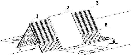
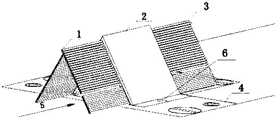
An experimental device for measuring the thickness of the airflow boundary layer near the wall of an inverted V-shaped aircraft

A technology of thickness measurement and experimental equipment, applied in the field of experimental mechanics, can solve the problems of difficulty in improving spatial resolution, complicated installation and operation, etc., and achieve the effect of simple structure, fine measurement and small space occupation

Active Publication Date: 2020-05-12
INST OF HIGH SPEED AERODYNAMICS OF CHINA AERODYNAMICS RES & DEV CENT
View PDF5 Cites 0 Cited by
  • Summary
  • Abstract
  • Description
  • Claims
  • Application Information

AI Technical Summary

Problems solved by technology

[0011] The object of the present invention is to provide an experimental device for measuring the thickness of the airflow boundary layer near the wall of an inverted V-shaped aircraft. The device is installed on the surface of the experimental model of the aircraft to be tested. The pressure measurement rake directly interferes with the flow field, and the pressure measurement pipelines are arranged staggered by the two branches of the inverted V-shaped measurement rake to improve the accuracy and reliability of the velocity test data in the boundary layer, and the two channels can also be adjusted reasonably The distance distribution function between the branch pressure measurement pipeline and the surface of the experimental model of the aircraft under test solves the problems of difficulty in improving the spatial resolution of the traditional pressure measurement rake test data and complicated installation and operation

Method used


Image

  • An experimental device for measuring the thickness of the airflow boundary layer near the wall of an inverted V-shaped aircraft
  • An experimental device for measuring the thickness of the airflow boundary layer near the wall of an inverted V-shaped aircraft
  • An experimental device for measuring the thickness of the airflow boundary layer near the wall of an inverted V-shaped aircraft

Examples


Embodiment Construction

[0046] All features disclosed in this specification, or steps in all methods or processes disclosed, may be combined in any manner, except for mutually exclusive features and / or steps.

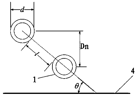
[0047] Such as figure 1 As shown, the device for measuring the thickness of the airflow boundary layer near the wall of the present invention includes a rake body and an air inlet pipe and an air outlet pipe arranged on the rake body, wherein the rake body is arranged on a flat plate model, and the flat plate model plays a supporting role. The rake body in the present invention changes the traditional single-sided straight plate shape, adopts a V-shaped structure, and changes the relative distance between the intake pipes through the V-shaped design, thereby reducing the influence on the state of the flow field.

[0048] In the present invention, the surface part of the V-shaped rake body exposing the flat plate model is a V-shaped thin plate with a thickness of 2mm. The distance from the sur...


PUM


Abstract

The invention discloses an experimental device for measuring the thickness of the near-wall airflow boundary layer of an inverted V-shaped aircraft. The experimental device comprises an experimental measuring pipe supporting platform and a measuring pipe main rake body arranged on the supporting platform. The rake body is provided with a number of intake and outlet pipes. The experimental deviceis arranged on the surface of an experimental model of the aircraft to be tested. The inverted V-shaped geometric shape of a pressure measuring rake is reasonably set, which reduces the direct interference of the pressure measuring rake body to a flow field. Two branch pressure measuring pipes of the inverted V-shaped measuring rake body are used to improve the accuracy and reliability of velocity test data in the boundary layer, wherein the measuring pipes are in staggered arrangement. The distance distribution function of two branch pressure measuring pipes and the surface of the experimental model of the tested aircraft can be reasonably adjusted. The problems of difficult improvement of test data spatial resolution, complicated installation and operation and the like of a traditional pressure measuring rake are solved.

Description

technical field [0001] The invention belongs to the technical field of experimental mechanics in aerospace, and in particular relates to an inverted V-shaped experimental device for measuring the thickness of the airflow boundary layer near the wall of an aircraft, which is mainly used for accurate measurement of the thickness of the boundary layer near the wall of an aircraft experimental model Acquisition of flow characteristic data. Background technique [0002] When air flows through the surface of an aerospace vehicle, there is always a thin layer of uneven velocity distribution close to the surface of the object. In the field of aerospace and fluid mechanics research, the area is called the boundary layer of the flow of aircraft objects. According to the theorem proposed by Prandtl and the general agreement of domestic and foreign scholars, in engineering, the thickness of the area where the fluid velocity on the surface of an object is less than or equal to 0.99 times...

Claims


Application Information

Patent Timeline
Patent Type & Authority Patents(China)
IPC IPC(8): G01B21/08
CPCG01B21/08
Inventor 杨党国周方奇王显圣高荣钊刘俊施傲杨野
Owner INST OF HIGH SPEED AERODYNAMICS OF CHINA AERODYNAMICS RES & DEV CENT
Learn More