Laser radar and manufacturing method thereof

A technology of laser radar and wave light, which is applied in the field of photoelectric detection, can solve the problems of reduced detection range, limited laser radar application, shortened laser radar detection distance, etc., achieves large detection distance, reduces production cost and process difficulty, and reduces energy density Effect

Active Publication Date: 2018-09-21
HESAI TECH CO LTD
View PDF5 Cites 4 Cited by
  • Summary
  • Abstract
  • Description
  • Claims
  • Application Information

AI Technical Summary

Problems solved by technology

[0005] However, the limitation of laser power will lead to the problem of shortening the de

Method used


Image

  • Laser radar and manufacturing method thereof
  • Laser radar and manufacturing method thereof
  • Laser radar and manufacturing method thereof

Examples


Embodiment Construction

[0030] It can be seen from the background art that the lidar in the prior art that meets the human eye safety standard has the problems of too short a detection distance and a too small detection range. Now combine an existing laser radar to analyze the reasons for the small detection distance:

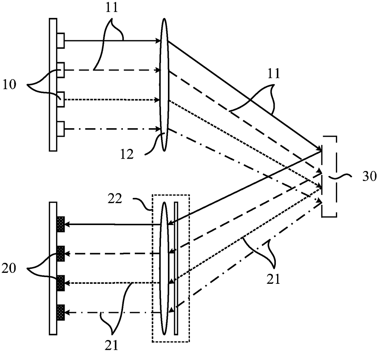
[0031] refer to figure 1 , shows a schematic diagram of the principle of a lidar.

[0032] Most of the existing laser radars adopt a separate arrangement of the emitting device and the detecting device. Moreover, in order to ensure the resolution of the laser radar, the transmitting device of the laser radar often includes a plurality of lasers 10 , that is, the laser radar is a multi-line laser radar.

[0033] Such as figure 1 As shown, the multi-line lidar includes a plurality of lasers 10 arranged in an array and a plurality of detectors 20 arranged in an array, and the plurality of detectors 20 corresponds to the plurality of lasers 10 one by one.

[0034] The working process ...


PUM


Abstract

The invention provides a laser radar and a manufacturing method thereof. Through mixed arrangement of emitter devices and detection devices, the laser radar not only reduces energy density of probe laser in a plane vertical to the light propagation direction and improves AELs.p.train limit of the laser radar, thereby achieving purposes of prolonging the laser radar detection distance and expandingthe laser radar detection range, but also reduces impact on existing laser radar paths as far as possible and prevents increasing the size of the laser radar, thereby achieving a purpose of controlling the manufacturing cost and process difficulty of the laser radar. The technical scheme can give consideration to high integration level and low process difficulty under the premise of ensuring highsafety and large detection distance.

Description

technical field [0001] The invention relates to the field of photoelectric detection, in particular to a laser radar and a manufacturing method thereof. Background technique [0002] The current LiDAR (Light Detection And Ranging, LiDAR) uses a semiconductor laser to emit laser pulses and then records the reflected light to create a point cloud map of the LiDAR's surroundings. [0003] However, laser safety regulations in various countries limit the power of laser pulses. According to the standards of human eye safety, the judgment of laser safety level is carried out under the most stringent judgment conditions under its normal working conditions. When the lidar rotates, the horizontal distance between two adjacent pulses is related to the rotational speed. When the rotational speed is larger, the horizontal distance deviation caused by the rotation is larger. In this case, the strictest judgment is based on a specific frequency. There are three limits that need to be c...

Claims


Application Information

Patent Timeline
IPC IPC(8): G01S7/481
CPCG01S7/481
Inventor 王瑞刘烨露吴世祥李娜向少卿李一帆
Owner HESAI TECH CO LTD
Why Eureka
Try Eureka