Reflective spatial filter debugging device and method

A space filter and reflective technology, which is applied in measuring devices, radiation pyrometry, instruments, etc., can solve problems such as space filter blocking, damage to laser drivers, and reduced safe operation of laser drivers, so as to improve the level of debugging , high wavefront measurement accuracy and simple structure

Active Publication Date: 2020-08-04
SHANGHAI INST OF OPTICS & FINE MECHANICS CHINESE ACAD OF SCI
View PDF1 Cites 0 Cited by
  • Summary
  • Abstract
  • Description
  • Claims
  • Application Information

AI Technical Summary

Problems solved by technology

Due to material dispersion, when a wide-spectrum laser beam is transmitted in a transmission-type spatial filter, the focal lengths of different wavelengths of laser light entering the lens are different, which can easily cause the hole of the spatial filter to be blocked, reduce the safe operation of the laser driver, and even seriously damage the laser. driver

Method used


Image

  • Reflective spatial filter debugging device and method
  • Reflective spatial filter debugging device and method
  • Reflective spatial filter debugging device and method

Examples


Embodiment Construction

[0032] The present invention will be further described below in conjunction with the accompanying drawings and embodiments, but the protection scope of the present invention should not be limited thereby.

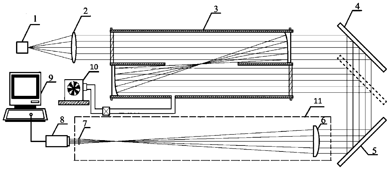
[0033] Such as figure 1 As shown, a debugging device for a reflective spatial filter includes a wide-spectrum fiber optic point light source 1, an achromatic collimator lens group 2, a first reflector 4, a second reflector 5, an achromatic beam shrinker lens group 11, Wavefront sensor 8, acquisition computer 9 and vacuum unit 10.

[0034] The optical elements along the beam direction output by the wide-spectrum fiber optic point light source 1 are the achromatic collimator lens group 2, the reflective spatial filter 3 to be debugged, the first mirror 4, and the second mirror 5. , Achromatic contraction lens group 11, wavefront sensor 8.

[0035] The wide-spectrum fiber optic point light source 1 is located at the focal point of the achromatic collimating lens group 2, and t...


PUM


Abstract

The invention relates to an optical system debugging device and method. The optical system debugging device comprises a wide spectral fiber spot light source, an achromatic collimating lens group, a reflective spatial filter to be debugged, reflectors, an achromatic beam compressing lens group, a wavefront sensor, an acquisition computer and a vacuum unit, uses a Hartmann sensor to detect the wavefront information of the output laser beam of the reflective spatial filter in real time, feeds back so as to perform precision adjustment on the input and output off axis paraboloidal mirrors of thespatial filter, and achieves the effect that the spatial filter can have the characteristics of being confocal and coaxial and outputting high beam quality. The optical system debugging device has thecharacteristics of simple structure, convenient debugging, real-time feedback of the beam wavefront information, high wavefront measurement accuracy and the like, can accurately estimate the qualityof the reflective spatial filter by using the measured beam wavefront information, can improve debugging level of the reflective spatial filter, and supports the technical application of the reflective spatial filter in ultra-short and ultra-intense laser devices.

Description

technical field [0001] The invention relates to an optical system debugging device and method, in particular to a reflection type spatial filter debugging device and method. Background technique [0002] Spatial filters are critical optical systems in laser drivers. It is used to suppress the nonlinear effect in the laser amplification process, improve the safe operation flux and efficiency of the system, filter and cut off the high-frequency information, and protect the laser working medium. Therefore, the performance of the spatial filter and its adjustment are crucial to the development and later operation of the laser driver. [0003] At present, there are two types in the field of high-power laser drivers: one is a high-energy laser system with a pulse width in the nanosecond to picosecond level and a pulse energy in the megajoule level; the other is a pulse width in the picosecond level. An ultra-short and ultra-intense laser system ranging from seconds to femtosecon...

Claims


Application Information

Patent Timeline
Patent Type & Authority Patents(China)
IPC IPC(8): G02B27/46G01J5/08
CPCG01J5/0831G02B27/46
Inventor 朱海东郭爱林胡恒春谢兴龙康俊杨庆伟高奇
Owner SHANGHAI INST OF OPTICS & FINE MECHANICS CHINESE ACAD OF SCI
Why Eureka
Try Eureka