
Orbital Angular Momentum (OAM) multiplexing transmission system based on phase surface relaying

An orbital angular momentum and transmission system technology, applied in the field of electromagnetic wave orbital angular momentum multiplexing transmission system, can solve the problem that the antenna array cannot directly sample and receive the ring phase plane.

Active Publication Date: 2018-09-21
TSINGHUA UNIV
View PDF8 Cites 13 Cited by
  • Summary
  • Abstract
  • Description
  • Claims
  • Application Information

AI Technical Summary

Problems solved by technology

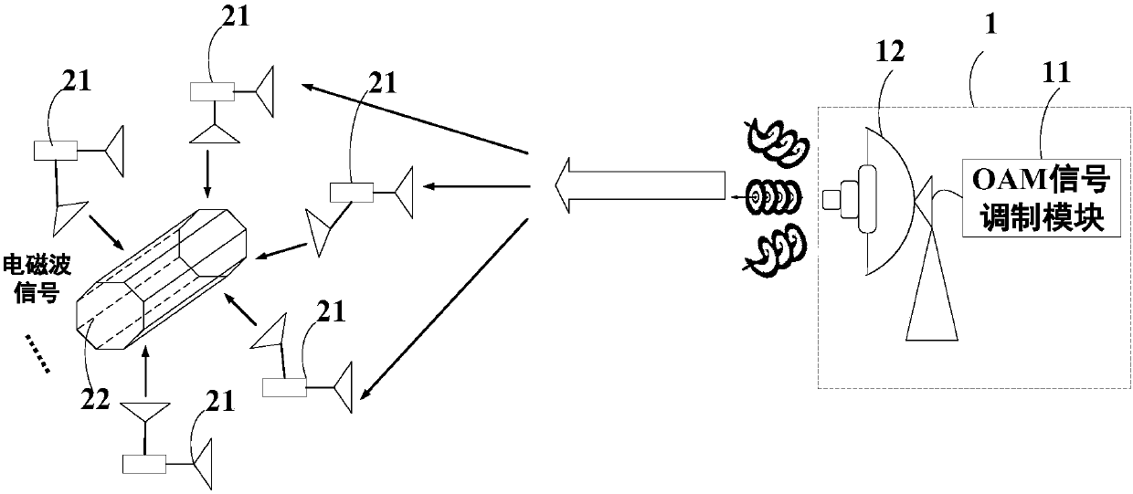
[0008] The electromagnetic wave orbital angular momentum multiplexing transmission system based on phase plane relay in the present invention adopts a distributed relay forwarding receiving mode at the signal receiving end, and distributes relay transponders on the entire ring covered by the main lobe , each relay transponder is independent of each other and does not interfere with each other. It relays and forwards the received signal on the entire ring phase plane. As the distance increases, the diameter of the ring formed by the main lobe in space gradually expands. After long-distance transmission (such as hundreds of kilometers), when it reaches the receiving end, the diameter of the ring is already quite large. At this time, the ordinary antenna array has already The problem that the direct sampling reception of the entire ring phase plane cannot be completed

Method used


Image

  • Orbital Angular Momentum (OAM) multiplexing transmission system based on phase surface relaying
  • Orbital Angular Momentum (OAM) multiplexing transmission system based on phase surface relaying
  • Orbital Angular Momentum (OAM) multiplexing transmission system based on phase surface relaying

Examples


Embodiment Construction

[0019] In the following description, for purposes of explanation, numerous specific details are set forth in order to provide a thorough understanding of one or more embodiments. It may be evident, however, that these embodiments may be practiced without these specific details. In other instances, well-known structures and devices are shown in block diagram form in order to facilitate describing one or more embodiments.

[0020] Various embodiments according to the present invention will be described in detail below with reference to the accompanying drawings.

[0021] figure 1 It is a block diagram of the electromagnetic wave orbital angular momentum multiplexing transmission system based on the phase plane relay of the present invention, such as figure 1 As shown, the electromagnetic wave orbital angular momentum multiplexing transmission system based on phase plane relay includes:

[0022] Signal transmitter 1, including:

[0023] OAM signal modulation module 11, user d...


PUM


Abstract

The invention discloses an orbital angular momentum (OAM) multiplexing transmission system based on phase surface relaying. The OAM multiplexing transmission system comprises a signal transmitting end, a signal receiving end and a central receiver, wherein the signal transmitting end is used for collecting user data, modulating the user data into OAM electromagnetic waves of a plurality of modes,and transmitting the OAM electromagnetic waves to the signal receiving end; the signal receiving end comprises a plurality of relay repeaters which are distributed on a circular ring covered by a mainlobe; each relay repeater forwards received signals at different locations on a phase plane circular ring; the relay repeaters are independent of each other, and the number of the relay repeaters isno less than the mode number of the OAM electromagnetic waves; the signals are forwarded to the central receiver in a wireless or wired way; the central receiver comprises a second receiving and transmitting antenna for receiving the signals relayed and forwarded by the plurality of relay repeaters, a phase plane correction module for carrying on phase plane correction on the distributed transmitted signals, and a demodulation module for demodulating the signals being subjected to phase plane correction. By adopting the system, electromagnetic wave orbital angular momentum transmission of longdistance, high capacity and high spectral efficiency can be realized.

Description

technical field [0001] The present invention relates to the technical field of wireless communication, and more specifically, to an electromagnetic wave orbital angular momentum multiplexing transmission system based on phase plane relay. Background technique [0002] Electromagnetic wave orbital angular momentum (Orbital Angular Momentum, OAM) is an inherent property of electromagnetic waves, and it is also another important physical quantity that is different from traditional electromagnetic wave frequency, electric field strength, etc. It is also called "vortex electromagnetic wave", phase plane and propagation direction Not vertical, showing spiral distribution. The commonly used conventional plane wave phase plane is perpendicular to the propagation direction, so it has no orbital angular momentum. [0003] The initial research on orbital angular momentum focused on optics. Allen et al. derived the expression of orbital angular momentum of light based on Maxwell's equa...

Claims


Application Information

Patent Timeline
IPC IPC(8): H04L27/26H04L5/00
CPCH04L5/0048H04L27/2649H04L27/2663H04L27/2697
Inventor 张超赵宇飞
Owner TSINGHUA UNIV
Learn More