Casting sand removing device

A technology for castings and sand boxes, which is applied in the field of casting desanding devices, can solve the problems of slow casting cleaning speed, low sand cleaning efficiency, and low processing efficiency, and achieve the goals of reducing manual labor, good sand removal effect, and improving efficiency Effect

Active Publication Date: 2018-09-25
YONGCHUAN DISTRICT CHONGQING HUAYI MACHINERY CASTING CO LTD
View PDF6 Cites 3 Cited by
  • Summary
  • Abstract
  • Description
  • Claims
  • Application Information

AI Technical Summary

Problems solved by technology

However, sand cleaning is a job with high labor intensity and harsh working environment in the casting industry, which will have a great impact on the health and safety of workers during the process of sand cleaning
Moreover, the cleaning speed of castings in this way is slow, the processing efficiency is very low, and the cost of cleaning is relatively high
[0003] At present, there are also some sand cleaning machines for sand cleaning. However, the ex

Method used


Image

  • Casting sand removing device
  • Casting sand removing device

Examples


Embodiment Construction

[0021] Further detailed explanation through specific implementation mode below:

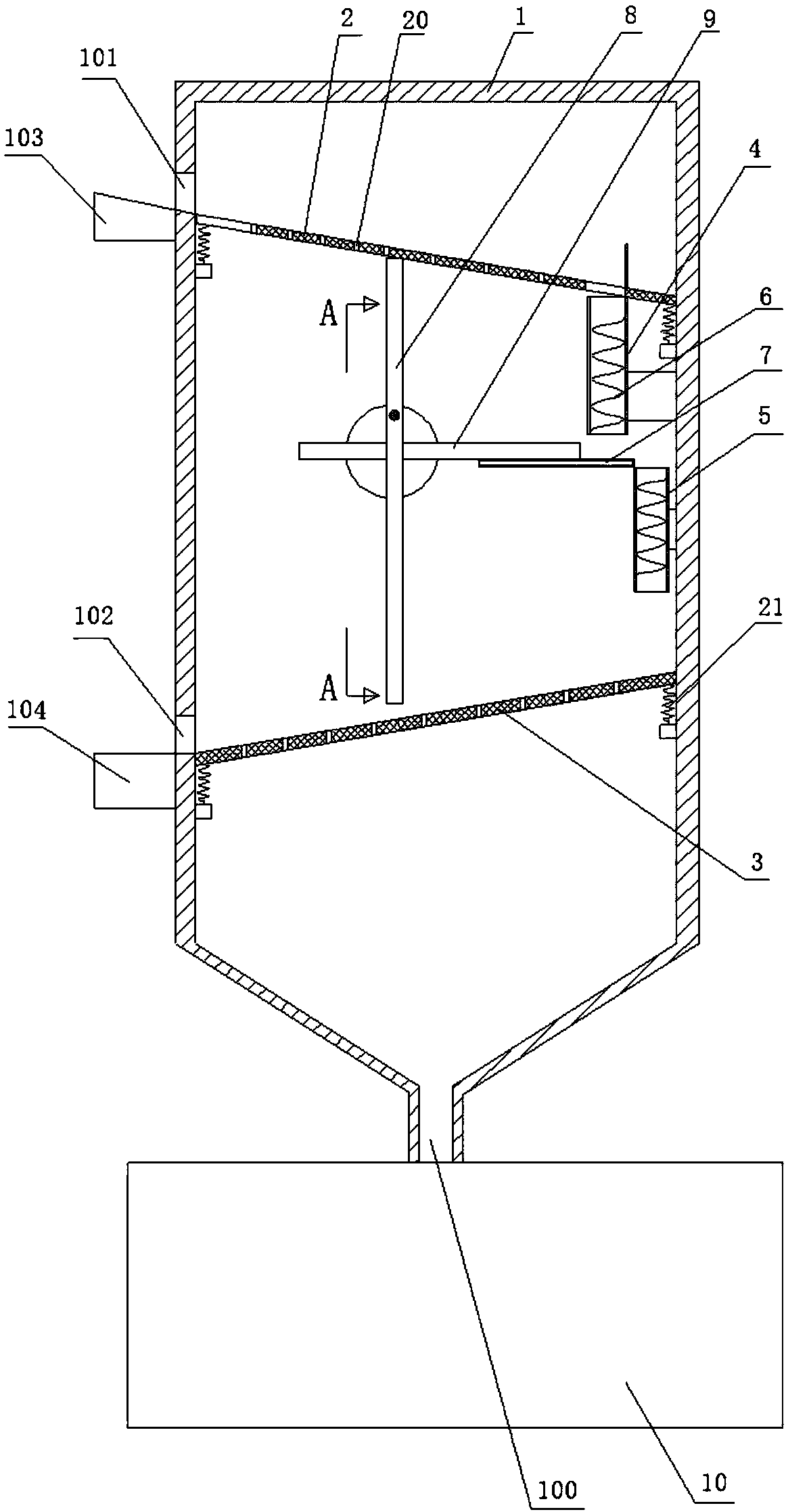
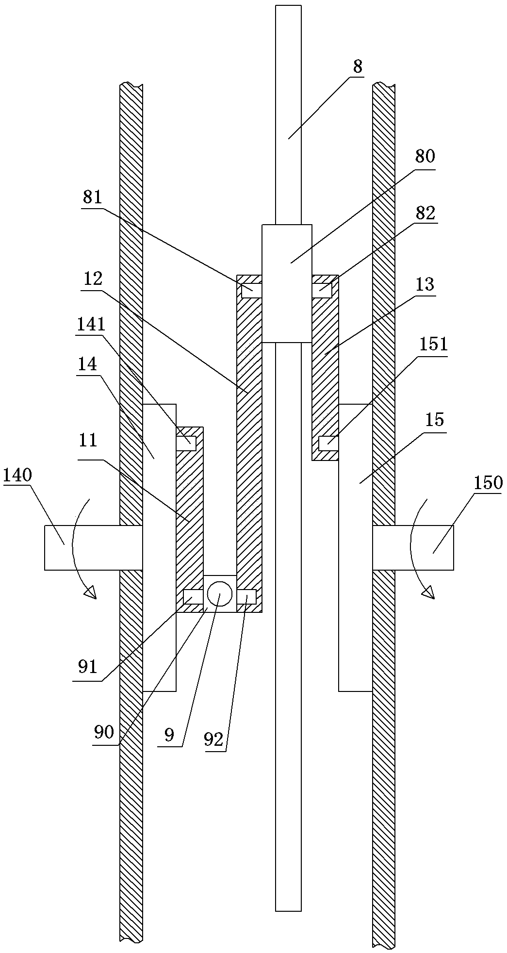
[0022] The reference signs in the drawings of the description include: sand removal box 1, sand discharge port 100, casting inlet 101, casting outlet 102, first support platform 103, second support platform 104, first movable plate 2, sand passage hole 20 , spring 21, second movable plate 3, first channel 4, second channel 5, protrusion 6, receiving groove 7, first push rod 8, first mounting sleeve 80, fourth round pin 81, third round pin 82. The second push rod 9, the second mounting sleeve 90, the sixth round pin 91, the fifth round pin 92, the collection box 10, the third crank 11, the second crank 12, the first crank 13, the second turntable 14, The second drive shaft 140 , the second round pin 141 , the first turntable 15 , the first drive shaft 150 , and the first round pin 151 .

[0023] Such as figure 1 As shown, a casting sand removal device in this embodiment includes a sand removal b...


PUM


Abstract

The invention belongs to the field of casting equipment, and particularly discloses a casting sand removing device. The casting sand removing device comprises a sand removing box; a horizontal first movable plate and a horizontal second movable plate are sequentially arranged in the sand removing box from top to bottom in a sliding manner; the first movable plate and the second movable plate are both inclined; the first movable plate and the second movable plate are inclined in opposite directions; sand through holes are formed in the first movable plate and the second movable plate; a first push rod is vertically connected between the first movable plate and the second movable plate in a sliding manner; the top end of the first push rod is propped against the first movable plate; the bottom end of the first push rod is propped against the second movable plate; a first passage is arranged at the low end of the first movable plate; a second passage is rotationally connected with the inner side wall of the sand removing box below the first passage; spiral bulges are arranged on the inner wall of the first passage and the inner wall of the second passage; bristles are densely distributed on the bulges; a receiving slot is arranged between the first passage and the second passage; and a second push rod is connected with the receiving slot in a sliding manner. The device can turn over automatically when used for sand removal of castings.

Description

technical field [0001] The invention relates to the field of casting equipment, in particular to a casting sand removal device. Background technique [0002] Sand cleaning of castings is a very important process in the casting process. At present, the work of sand cleaning is generally carried out by manual sand cleaning. However, sand cleaning is a job with high labor intensity and harsh working environment in the casting industry, which will have a great impact on the health and safety of workers in the process of sand cleaning. Moreover, the cleaning speed of castings in this way is relatively slow, the processing efficiency is very low, and the cost of cleaning is relatively high. [0003] At present, there are also some sand cleaning machines for sand cleaning. However, the existing sand cleaning machines still need to manually put the castings in place during the sand cleaning process. In order to remove sand more thoroughly, the castings often need to be manually tu...

Claims


Application Information

Patent Timeline
IPC IPC(8): B22D31/00
CPCB22D31/002
Inventor 孔锐
Owner YONGCHUAN DISTRICT CHONGQING HUAYI MACHINERY CASTING CO LTD
Why Eureka
Try Eureka