Plate cutting device for metal product machining

A technology for metal products and metal plates, applied in metal processing equipment, metal processing mechanical parts, shearing devices, etc., can solve the problems of low degree of automation of cutting operations, inability to achieve equidistant automatic cutting effect of metal plates, etc. The effect of manual labor, improving cutting efficiency and high degree of automation

Inactive Publication Date: 2020-08-07
长兴锐锋机械有限公司
View PDF1 Cites 14 Cited by
  • Summary
  • Abstract
  • Description
  • Claims
  • Application Information

AI Technical Summary

Problems solved by technology

[0003] The patent application publication No. CN107891177 A discloses a cutting device for metal products after printing, including a base, hydraulic devices are installed at the four corners of the top of the base, and a cutting device is installed on the left side of the inner cavity of the die. The cutting device includes a fixed frame, a motor is installed on the top of the fixed frame, and a rotating shaft is installed on the output shaft of the motor. The rotating shaft is connected to the rotating shaft through a rotating belt, and the left and right sides of the inner wall of the rotating shaft are provided with propulsion grooves. A fixing plate is installed on the pushing groove close to the inner wall of the rotating shaft, a pushing spring is installed on the side of the fixing plate away from the inner wall of the rotating shaft, and a cutting knife is installed on the other end of the pushing spring. precision, although the device can be used for cutting metal products, but the degree of automation of the cutting operation is low, and it cannot realize the equidistant automatic cutting effect on metal plates. For this reason, a metal product processing Use a plate cutting device to solve the above technical problems

Method used


Image

  • Plate cutting device for metal product machining
  • Plate cutting device for metal product machining
  • Plate cutting device for metal product machining

Examples


Embodiment 1

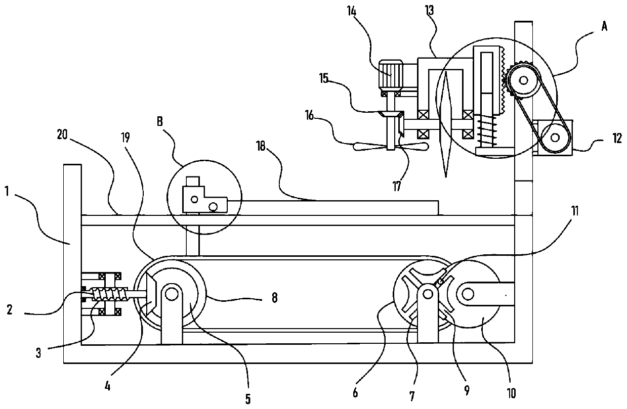
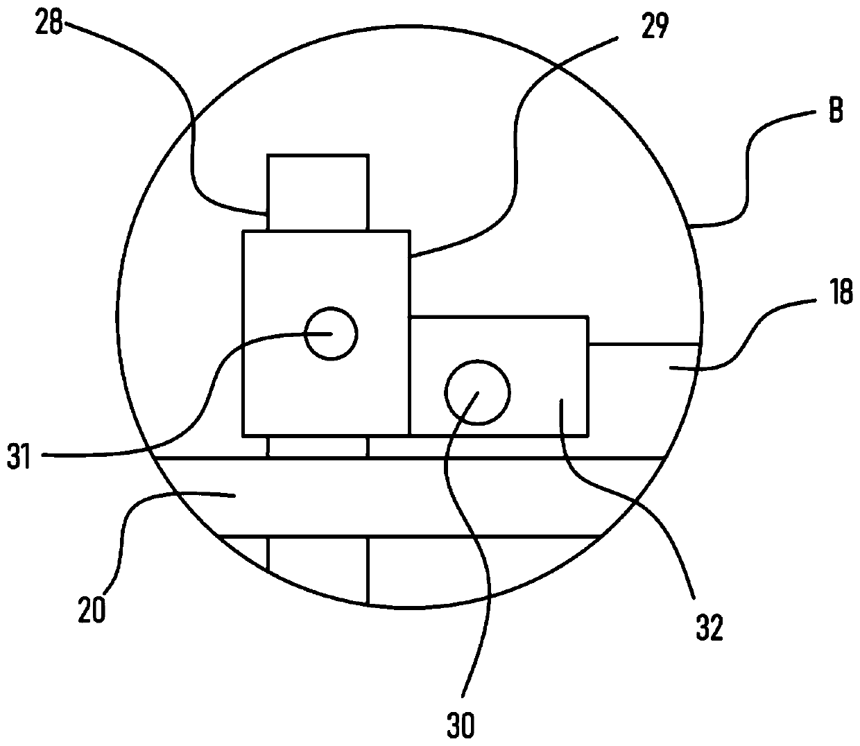
[0025] see Figure 1-4 , a plate cutting device for processing metal products, comprising a support frame 1, a support plate 20 is horizontally fixed on the support frame 1, a clamping mechanism for clamping a metal plate 18 is provided on the support frame 1, and a The runner I6 and the runner II8 located below the support plate 20 are rotated and installed, the runner I6 and the runner II8 are sleeved with a transmission belt 19, and the support plate 20 is provided with a strip-shaped through hole 33 in a horizontal direction. There is a push plate 28 vertically running through the through hole 33, one end of the push plate 28 is fixedly connected with the clamping mechanism, the other end of the push plate 28 is fixed on the transmission belt 19, and the support frame 1 is provided with a stepping wheel for driving the runner 16. The stepping mechanism of the mechanism, the support frame 1 is provided with a cutting mechanism for cutting the metal plate 18, and the support...

Embodiment 2

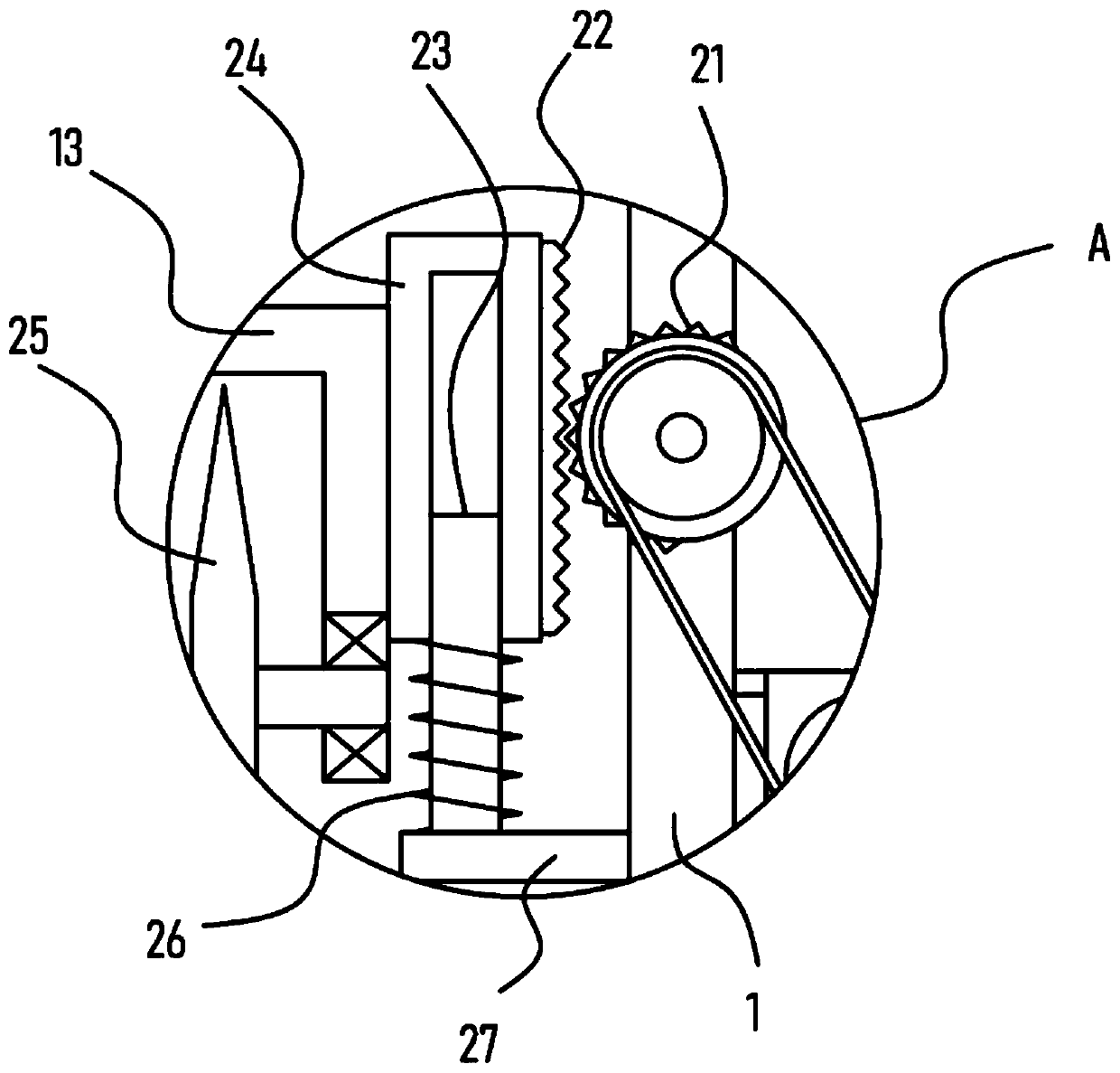
[0031] On the basis of Embodiment 1, in addition, the cutting mechanism includes a lifting frame 13, and a motor II14 is fixed on the side wall of the lifting frame 13, and the output shaft of the motor II14 is coaxially fixed with a driving bevel gear 15, and the driving bevel gear 15 is meshed with a The driven bevel gear 17 is coaxially fixed with a blade 25 on the driven bevel gear 17 .

[0032] The motor II14 drives the driving bevel gear 15 to rotate, and the driving bevel gear 15 drives the driven bevel gear 17 meshed with it to rotate, thereby realizing the rotation of the blade 25, and the lifting mechanism drives the elevating frame 13 to move downward, so that the blade 25 is aligned with the metal plate 18. Perform cutting.

[0033] In addition, an axial flow fan 16 is connected to the driving bevel gear 15 through transmission, and the axial flow fan 16 is driven to rotate during the rotation of the driving bevel gear 15. During the rotation of the axial flow fan ...


PUM


Abstract

The invention discloses a plate cutting device for metal product machining, and relates to the technical field of metal product machining. The plate cutting device comprises a supporting frame; a supporting plate is horizontally fixed to the supporting frame, a push plate vertically penetrates through a strip-shaped through hole, one end of the push plate is fixedly connected with a clamping mechanism, and the other end of the push plate is fixed to a conveying belt; a stepping mechanism used for driving a rotating wheel I is arranged on the supporting frame, a cutting mechanism used for cutting a metal plate is arranged on the supporting frame, and a lifting mechanism used for driving the cutting mechanism to move vertically is arranged on the supporting frame. According to the plate cutting device for the metal product machining, the metal plate is cut through the arranged cutting mechanism, the arranged stepping mechanism can drive the clamping mechanism to drive the metal plate todo transverse equal-interval stepping movement, the lifting mechanism drives a blade in the cutting mechanism to vertically ascend and descend in a reciprocating mode, and the equal-interval automaticcutting effect on the metal plate is achieved; and the cutting efficiency of the metal plate is greatly improved, the automation degree is high, and the manual labor amount is greatly reduced.

Description

technical field [0001] The invention relates to the technical field of metal product processing, in particular to a plate cutting device for metal product processing. Background technique [0002] The metal product industry includes structural metal product manufacturing, metal tool manufacturing, container and metal packaging container manufacturing, stainless steel and similar daily-use metal product manufacturing, etc. With the progress of society and the development of science and technology, metal products are used more and more widely in various fields of industry, agriculture and people's lives, and also create more and more value for society. In the process of processing and manufacturing metal products, it is necessary to The used sheet metal parts are cut into pieces for further batch processing. [0003] The patent application publication No. CN107891177 A discloses a cutting device for metal products after printing, including a base, hydraulic devices are instal...

Claims


Application Information

Patent Timeline
Patent Type & Authority Applications(China)
IPC IPC(8): B23D19/00B23D33/02B23D33/00B23Q5/22B23Q5/28
CPCB23D19/00B23D33/00B23D33/02B23Q5/22B23Q5/28
Inventor 许华
Owner 长兴锐锋机械有限公司
Why Eureka
Try Eureka