Enclosed composite member forming tool and application method thereof

A composite material component and forming tooling technology, applied in the application, household components, household appliances and other directions, can solve the problems of difficult processing of split forming tooling, affecting the appearance quality of the parts, reducing the service life and other problems, so as to shorten the demoulding time. , the effect of improving service life and reducing manufacturing costs

Active Publication Date: 2018-09-25
AVIC BASIC TECH RES INST
View PDF2 Cites 8 Cited by
  • Summary
  • Abstract
  • Description
  • Claims
  • Application Information

AI Technical Summary

Problems solved by technology

Split-type molding tooling is difficult to process, high in cost, and there is a step difference between the split parts, which affects the appearance quality of the part
During use, due to repeated use of positioning pins and bolts and other fasteners, it is easy to cause damage to the mold and greatly reduce the service life

Method used


Image

  • Enclosed composite member forming tool and application method thereof
  • Enclosed composite member forming tool and application method thereof
  • Enclosed composite member forming tool and application method thereof

Examples


Embodiment 1

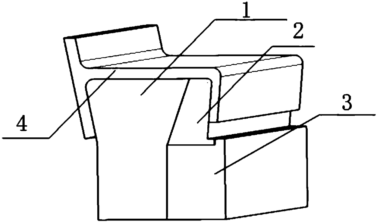
[0022] For the "J" type composite beam, the length is 11.8 meters, the angle between the edge strip and the web in the non-open area is 84.5°, there is a large closure, and it is difficult to demould. Adopt the forming frock design scheme of the present invention, the closed area is split, and the split angle is 60°, which ensures that the split frock 2 is open and can be pulled out from the mold (see attached figure 2 ). After the mold is cleaned first, the split tooling 2 is placed on the bottom bracket 3, and the bottom bracket 3 is placed close to the split tooling 1, and then the prepreg is laid up. After the parts are solidified, demoulding is carried out, and the bottom support 3 is removed from the mold in a horizontal direction, so that the split tooling 2 is in a suspended state. Then slide the split tooling 2 downwards out of the inner cavity of the part, gently tap the composite material part to separate it from the split tooling 1, and remove the part to complet...

Embodiment 2

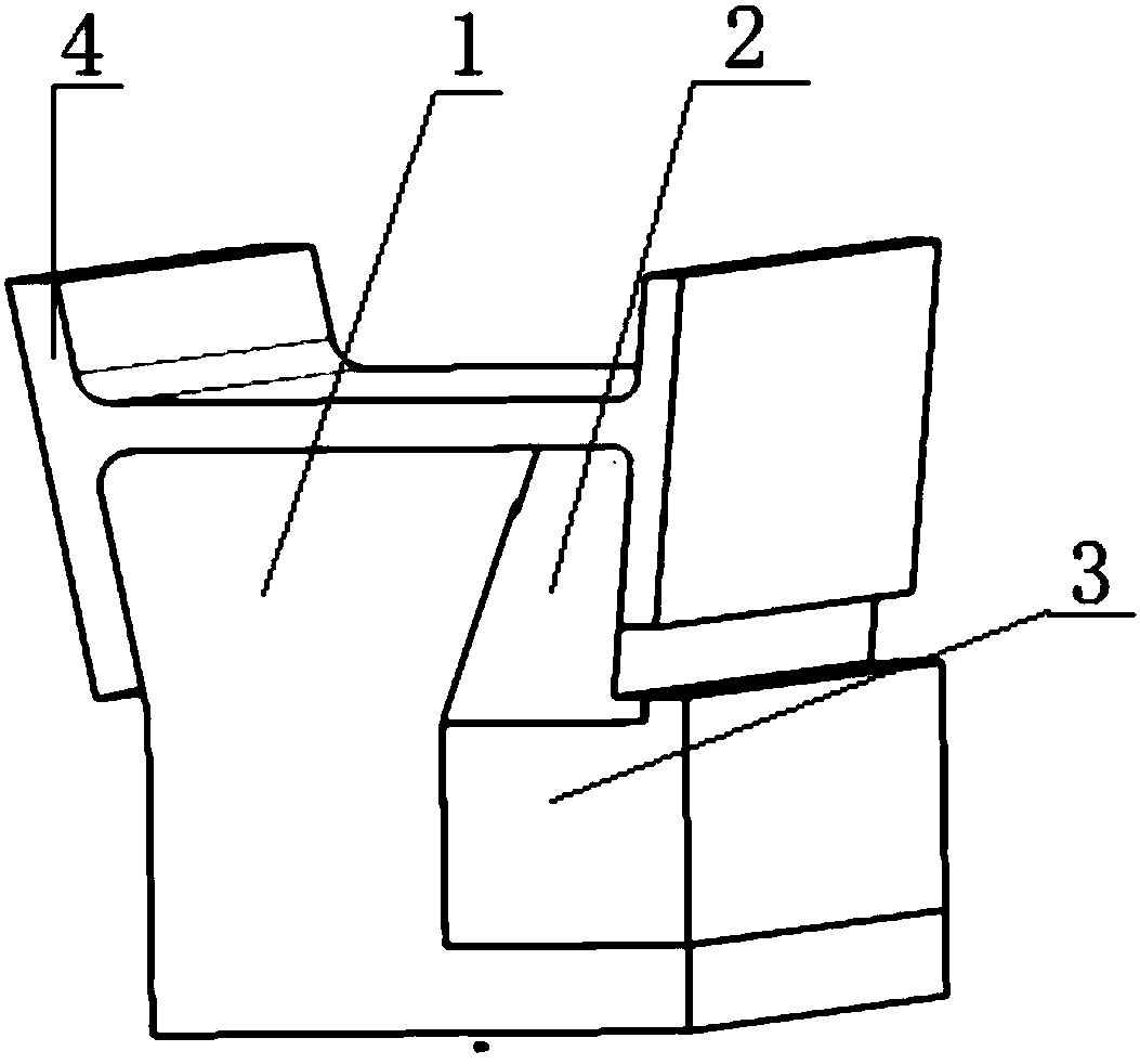
[0024] For the "I" type composite rib, the angle between the edge strip and the web in the non-open area is 83.3°, there is a large closure, and it is difficult to demould. Adopt the mold design of the present invention, the closing area is carried out split body, guarantee that the split frock 2 is open, can deviate from the mould (see attached image 3 ). After the mold is cleaned first, the split tooling 2 is placed on the bottom bracket 3, and the bottom bracket 3 is placed close to the split tooling 1, and then the prepreg is laid up. After the parts are solidified, demoulding is carried out, and the bottom support 3 is removed from the mold in a horizontal direction, so that the split tooling 2 is in a suspended state. Then slide the split tooling 2 down from the inner cavity of the part, gently tap the composite material part to separate it from the split tooling 1, and then take the part out of the main tooling to complete the part manufacturing

Embodiment 3

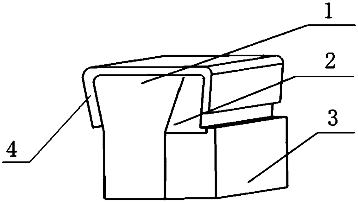
[0026] For the "C" type composite beam, the length is 6.2 meters, and the angle between the edge strip and the web in the non-open area is 81.5°, there is a large closure, and it is difficult to demould. Adopt the mold design of the present invention, the closed area is split, and the split angle is 63 °, which ensures that the split frock 2 is open and can be released from the mold (see attached figure 1 ). After the mold is cleaned first, the split tooling 2 is placed on the bottom bracket 3, and the bottom bracket 3 is placed close to the split tooling 1, and then the prepreg is laid up. After the parts are cured, demoulding is carried out. First, the bottom bracket 3 is removed from the molding tool along the direction perpendicular to the length of the part, so that the split tooling 2 is in a suspended state. Then the split tooling 2 is slid downwards out of the inner cavity of the part, and the composite material part is gently tapped to separate it from the split tool...


PUM


Abstract

The invention belongs to the technical field of composite member forming and relates to an enclosed composite member forming tool and an application method thereof. The invention is intended to overcome the defect that separate forming tooling for traditional enclosed composite members uses a great amount of positioning pins and fastening bolts; the enclosed composite member forming tool depends on base positioning and fully avoids the use of positioning fasteners, such as positioning pins and bolts, such that manufacture cost of the tool is greatly reduced, and tool manufacture cycle is shortened. A demolding process has no need for removal of bolts and positioning pins, demolding time is greatly shortened, the technical requirement on the demolding process is lowered, and production efficiency is improved. The enclosed composite member forming tool has good positioning simplicity, has very low damage repair rate, and has greatly extended service life.

Description

technical field [0001] The invention belongs to the technical field of composite material component forming, and relates to a closed composite material component forming tool and a use method thereof. Background technique [0002] With the development of aviation manufacturing technology, the amount of composite materials on the new generation of large passenger aircraft exceeds 50%, and it has transitioned from traditional non-bearing parts and secondary load-bearing parts to main load-bearing parts. Due to the aerodynamic shape and force requirements of aerospace vehicles, there are a large number of closed structures in aerospace composite components, such as beams, ribs, long trusses, side strips, etc. Since the angle between the web surface and the edge surface of this structure is less than 90°, it is difficult to demould after curing. [0003] For the closed structure, the traditional molding tooling generally adopts a split type, which is connected together by faste...

Claims


Application Information

Patent Timeline
Patent Type & Authority Applications(China)
IPC IPC(8): B29C70/30B29C70/54B29C33/00B29L31/30
CPCB29C33/00B29C70/30B29C70/54B29L2031/3082
Inventor 邱启艳荀国立陈静
Owner AVIC BASIC TECH RES INST
Why Eureka
Try Eureka