Plastic bag bundling machine

A strapping machine and plastic bag technology, which is applied to strapping machine parts, strapping materials, paper product packaging, etc., can solve problems such as lack of elasticity, weak connection points, and low efficiency

Inactive Publication Date: 2018-09-25
王秀来
View PDF4 Cites 5 Cited by
  • Summary
  • Abstract
  • Description
  • Claims
  • Application Information

AI Technical Summary

Problems solved by technology

The problems in comparative document 1 are: first, the binding method of comparative document 1 is to use two binding straps for binding, and there are two binding straps and two connecting points on the binding line of each plastic bag, and the more connecting points The weaker it is, and it also affects the appearance
Second, because the plastic strapping is almost inelastic, the strapping must be torn when opening the plastic bag, and once it is torn open, it cannot be bundled any more
Moreover, the binding procedure of Comparative Document 2 is cumbersome, and the structure of the binding device is complicated. It is necessary to prefabricate a rubber ring on the binding barrel, and then put the rubber ring on it, and then fix the plastic bag with a pressure plate after putting on the rubber ring, and then The bag passing manipulator is then pulled out to meet the next strapping procedure, which is inefficient

Method used


Image

  • Plastic bag bundling machine
  • Plastic bag bundling machine
  • Plastic bag bundling machine

Examples


Embodiment 1

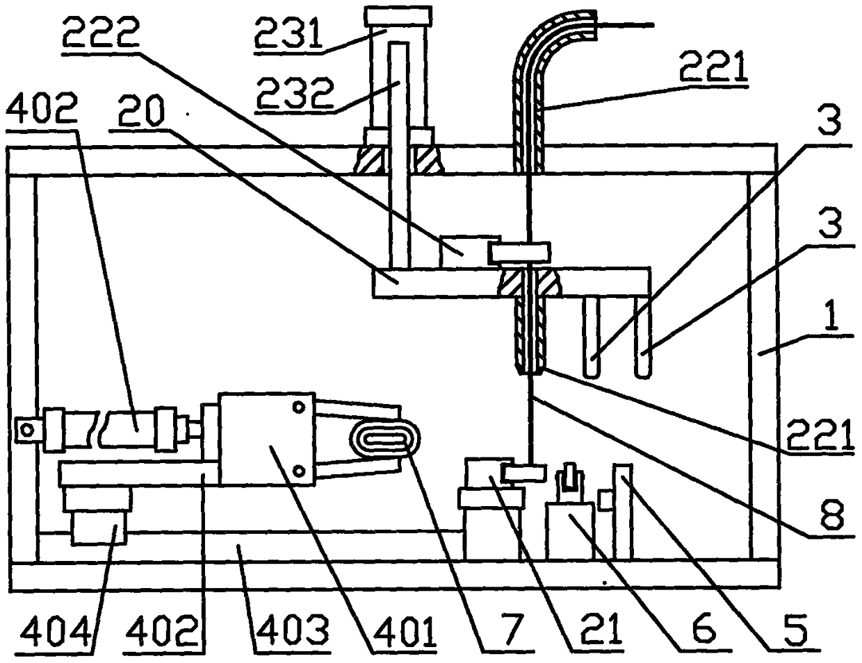
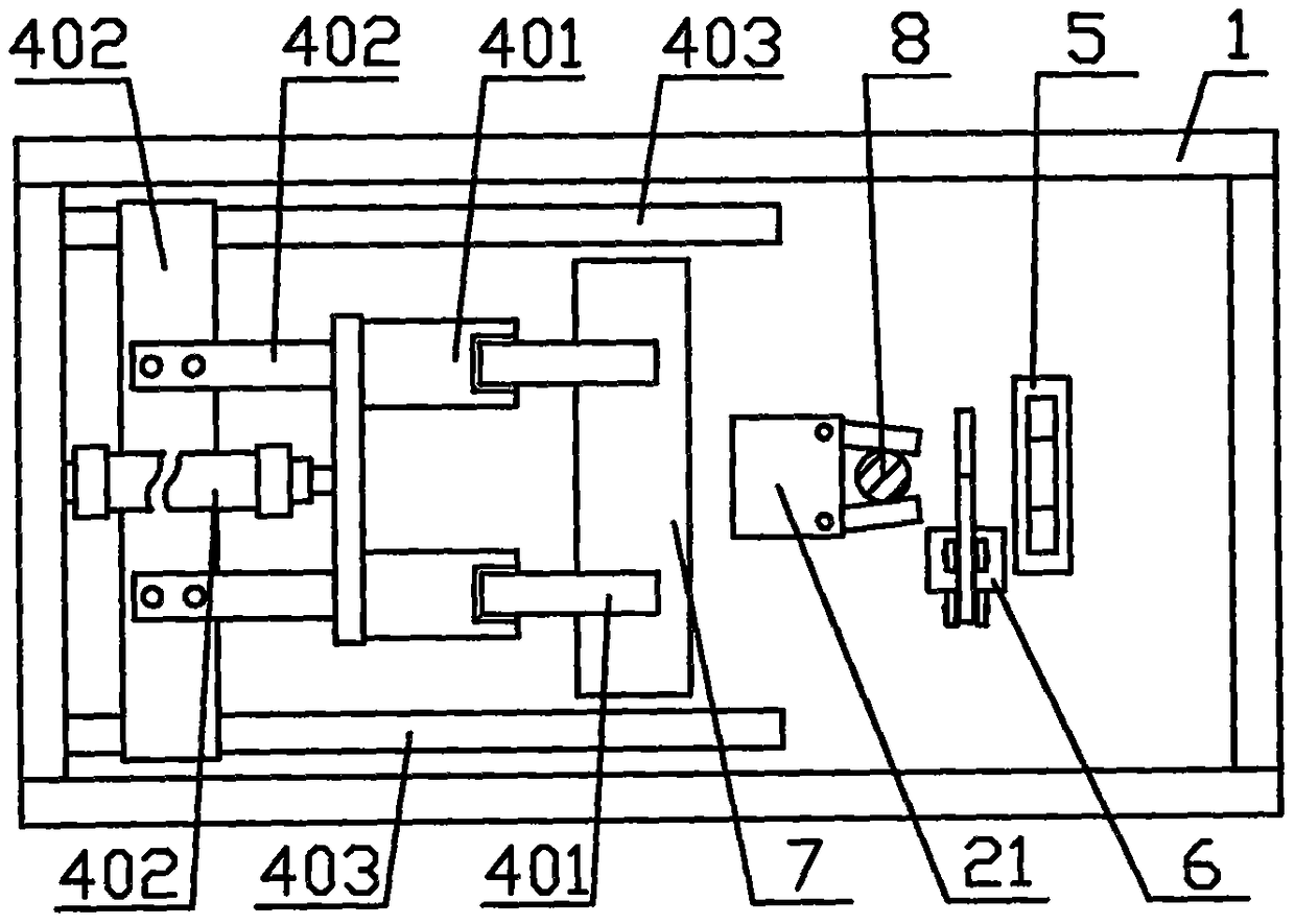
[0066] Embodiment one, such as figure 1 , figure 2 Shown: pay-off device 2 comprises pull wire clip 21, pay-off valve 22, pay-off seat 20, pay-off driving mechanism 23. Its lead wire clamp 21 is a kind of pneumatic finger, and described pneumatic finger 21 is fixedly connected on the described frame 1; Described wire release valve 22 is made of two wire release nozzles 221 and wire release clamp 222, and described The pay-off clamp 22 is a pneumatic finger, a pay-off nozzle 221 and a pay-off clamp 22 are installed on the pay-off seat 20, that is, the pay-off valve is connected to the pay-off seat 20, and the draw-off clip 21 and the release valve 22 are up and down correspond. The pay-off driving mechanism 23 includes a cylinder 231 and a guide rod 232 . The bag passing device 4 is a manipulator mechanism 40, which is arranged on one side of the wire releasing device 2, that is, in front of the wire releasing device; the rear side of the bag passing device 2 is also provid...

Embodiment 2

[0074] Embodiment two, such as Figure 17 to Figure 20 Shown: the difference between embodiment two and embodiment one is: one is that bag passing device is a kind of conveyor belt mechanism, and its structural principle is identical with the conveyor belt mechanism of folding device A. The conveyor belt mechanism is composed of two drive rollers 421, a conveyor belt 42, a swing rod 422, and a swing cylinder 423; The heat-sealing device that constitutes, omits close together plate 3; The 3rd, draw wire clip 21 is made of double-rod cylinder 226 and fixed block 227, and the release clip 22 is made of double-rod cylinder 224 and fixed block 225; The 4th, cutting device 6 is a kind of Eager cutter 66; The 5th, pay-off driving mechanism is a kind of electric slide table 233;

[0075] Such as Figure 17 As shown: an electric slide 223 is installed up and down the frame 1, a pay-off seat 20 is connected to the slide 235 of the electric slide 233, and a biaxial cylinder 224 and a f...

Embodiment 3

[0077] Embodiment three, such as Figure 21 with Figure 22 Shown: the difference between the third embodiment and the first embodiment is: first, the wire clamp 21 is connected on the wire release seat 20, and the miniature cylinder 223 and the wire release nozzle 221 of the wire release valve are fixedly connected on the frame 1, The said pay-off driving mechanism is another electric slide table 233, the pay-off seat 20 is connected on the slide table 235 of the electric slide table 233, and the wire clamp 21 corresponds up and down with the pay-off nozzle 221 of the pay-off valve; The bag device is arranged on the same side of the cutting device 6 and the connecting device 5 and the closing plate 3. The bag passing device is a mechanical arm 41; Body; Its three, cutting device 6 is a kind of pneumatic scissors. Such as Figure 21 As shown: a mechanical arm 41 is installed behind the cutting device 6 and the connecting device 5. The mechanical arm 41 is a conveying device...


PUM


Abstract

The invention discloses a plastic bag bundling machine. Plastic bags are bundled by adopting linear elastic rubber bands. The plastic bag bundling machine mainly comprises a rack, a pay-off device, abag transfer device, a connecting device, a cutting device and a doubling plate, wherein one end of a bundling line is fixed by a wire pulling clamp of the pay-off device; a pay-off valve reciprocatesrelative to the wire pulling clamp under drive of a pay-off driving mechanism so as to release one section of needed bundling line; the bag transfer device is used for transferring plastic bags to the rear of the connecting device by virtue of the pay-off device; the bundling line is wound on the plastic bags in a V shape in the transfer process, and after a pay-off mouth and the doubling plate move downwards, the bundling line further draws close, the connecting device is used for connecting two strands of bundling lines drawing close to form an O-shaped ring, the cutting device is used forcutting off positions of the bundling lines outside the connecting points, and the operation of bundling of the plastic bags is completed. The plastic bag bundling machine disclosed by the invention is simple in structure and high in efficiency.

Description

technical field [0001] The invention relates to a plastic bag binding machine, in particular to a binding device which uses a linear elastic rubber band as a binding line to bind folded plastic bags. Background technique [0002] The plastic bags produced by the bag making machine are generally placed on the pallet with dozens of bags as a stack. In order to facilitate storage, transportation, sales and use, these stacks of plastic bags generally need to be folded three or four times, folded into strips, and then tied with rubber bands in the middle of the folded strips of plastic bags . Authorized notification number CN102167172 B", discloses an invention patent called a fully automatic folding and binding machine for plastic bags (hereinafter referred to as reference document 1). The binding device involved in reference document 1 is mainly composed of a folding plate, a clamping device, Consisting of two belt feeding devices and a heat sealing device, plastic strips are...

Claims


Application Information

Patent Timeline
Patent Type & Authority Applications(China)
IPC IPC(8): B65B13/06B65B13/18B65B61/06B65B27/08
CPCB65B13/06B65B13/18B65B27/08B65B61/06
Inventor 王秀来
Owner 王秀来
Why Eureka
Try Eureka