
Aeration pipe structure

A technology of aeration tube and tube body, which is applied in water aeration, sustainable biological treatment, water/sludge/sewage treatment, etc. It can solve the problems of high equipment cost, reduced bubble function, energy consumption, etc., and achieve cost reduction And equipment costs, increase the service life, reduce the effect of manufacturing costs

Inactive Publication Date: 2018-09-25
林秀美
View PDF8 Cites 1 Cited by
  • Summary
  • Abstract
  • Description
  • Claims
  • Application Information

AI Technical Summary

Problems solved by technology

[0005] In view of this, in order to improve the background technology, the existing aeration tubes have the characteristics of easy aging, cracking, enlarged pores, reduced function of making air bubbles, complicated manufacturing procedures, time-consuming and labor-intensive costs, large pores, low oxygen transmission, Poor oxygen transmission function, uneven aeration, high equipment cost, high energy consumption, high power demand, and easy occurrence of backflow, which may cause system blockage or even damage, etc.

Method used


Image

  • Aeration pipe structure
  • Aeration pipe structure
  • Aeration pipe structure

Examples


Embodiment Construction

[0026] In order to enable your examiner to have a further understanding and recognition of the features and features of the present invention, the following preferred embodiments are now listed and described as follows in conjunction with the drawings:

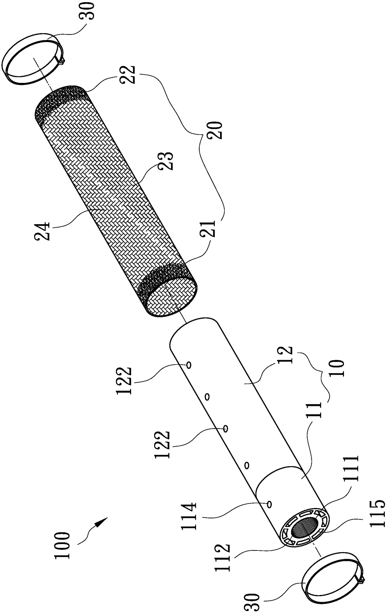
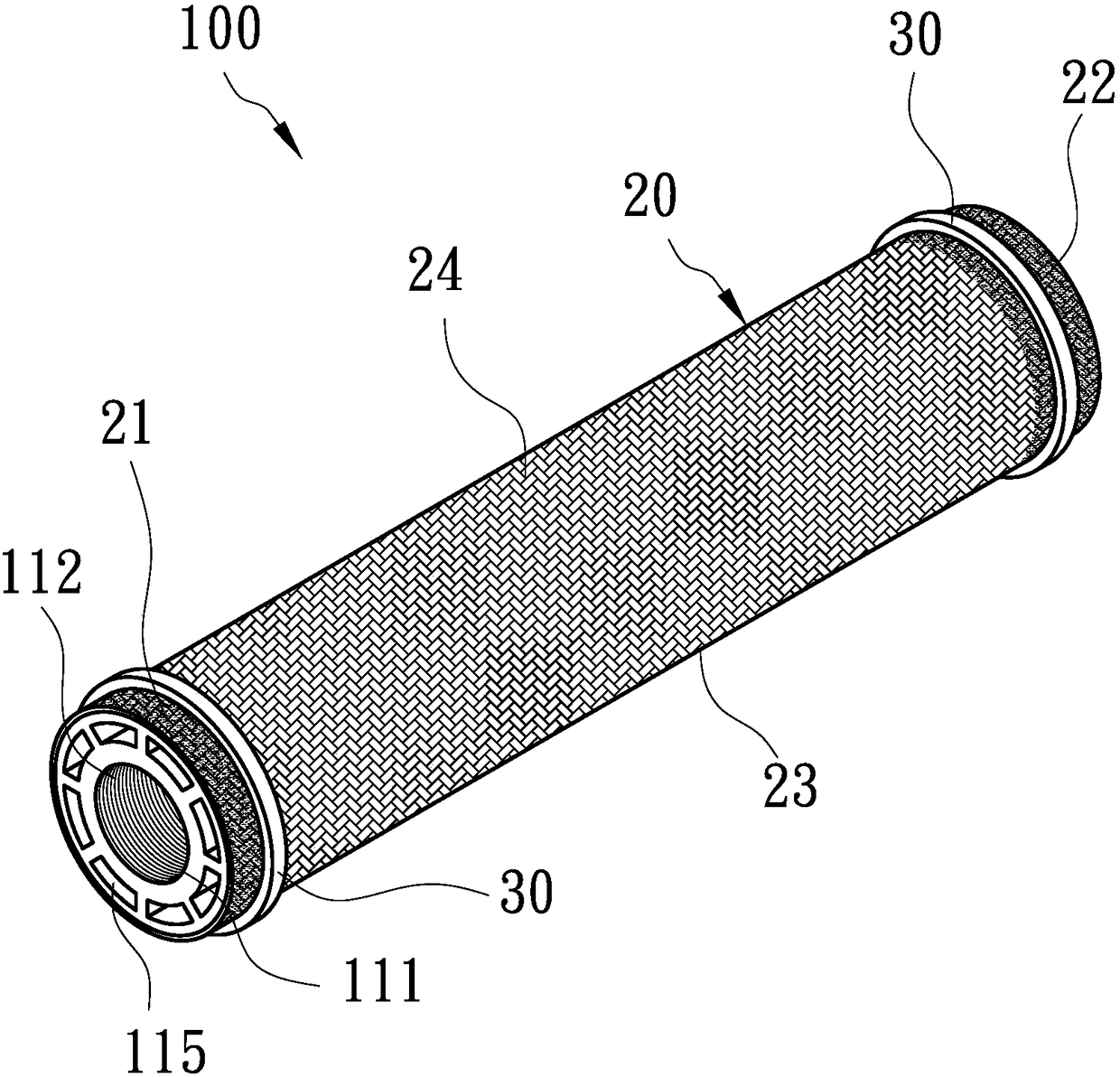
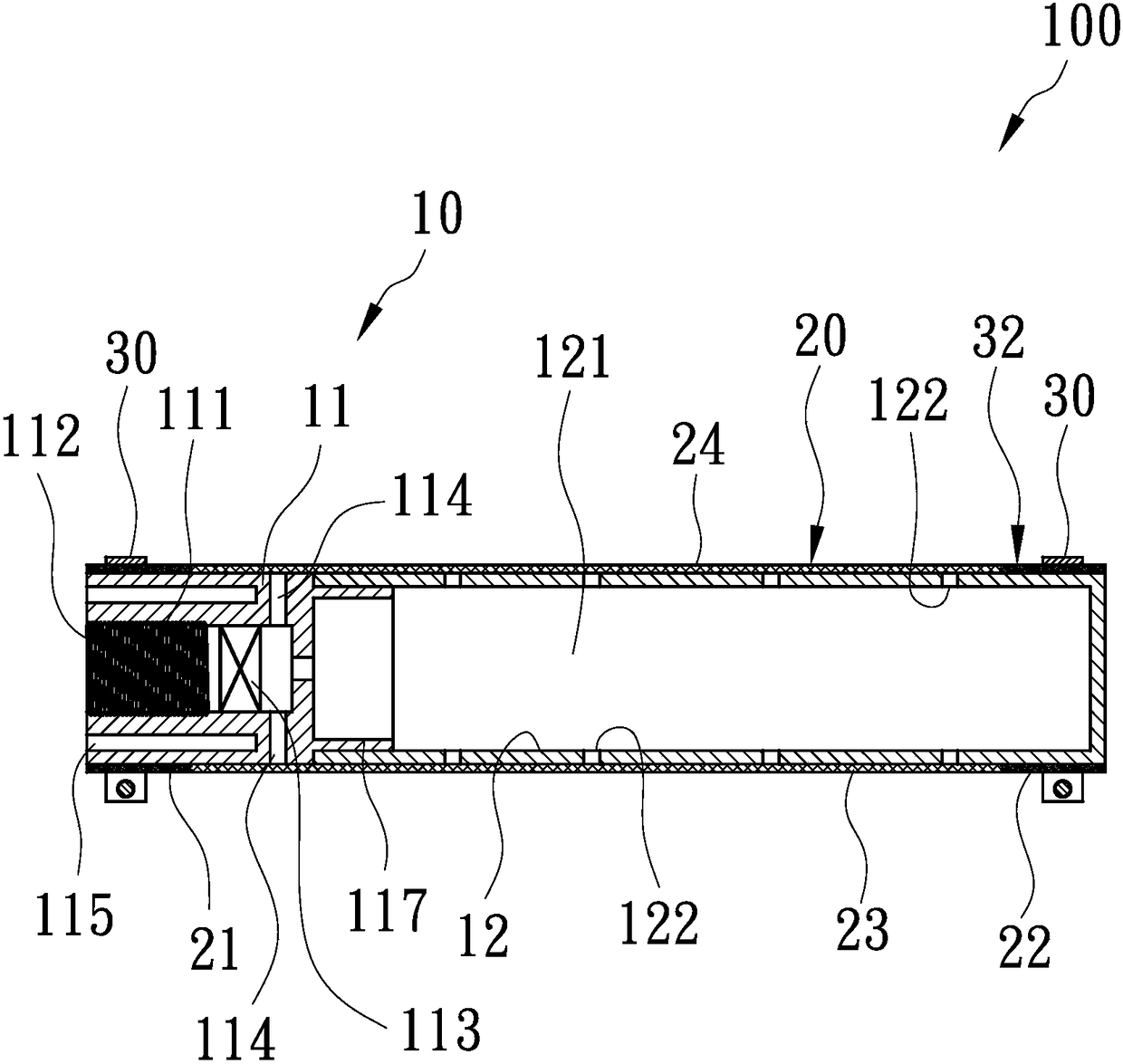
[0027] see Figure 1-Figure 8 , is an aeration pipe structure 100 provided by a preferred embodiment of the present invention, which includes a pipe body 10, a braided sheath 20 and two bundle rings 30, wherein:

[0028] see Figure 1-Figure 4 , the tube body 10 has a connector 11 and an inner tube 12 . The axis of the connector 11 has an air guide hole 111 that runs through the front and rear ends. The inner wall of the front section of the air guide hole 111 has an internal thread 112. A check valve 113 is arranged in the rear section of the air guide hole 111. By the air guide hole 111 After air supply, the fluid can only enter from the front section of the air guide hole 111 to the rear section, but cannot enter from the...


PUM


Abstract

The invention provides an aeration pipe structure. The aeration pipe structure comprises a pipe body, which has a gas chamber therein, wherein the front end of the pipe body has a gas guiding hole communicating with the air chamber, an internal thread and a check valve are arranged in the gas guiding hole, and the pipe body is radially provided with a plurality of pipe body pores allowing the outside to communicate with the gas chamber; and a braided sleeve, which can define a front section, a rear section and an intermediate section connected with and arranged between the front section and the rear section, wherein the front section, the rear section and the intermediate section of the braided sleeve are in braided shapes, the intermediate section has a plurality of braided pores, the braided sleeve coats the periphery of the pipe body, and the front section and the rear section are fixed on the pipe body. Gas enters the gas chamber from the gas guiding hole and is then released intothe braided sleeve by the pipe body pores, and dense and fine bubbles are sprayed out from the braided pores so as to increase oxygen transmission, reduce energy and power consumption, lower cost andequipment cost, prolong service life and prevent sewage from flowing backward.

Description

technical field [0001] The invention relates to water purification equipment, more specifically, to an aeration tube structure. Background technique [0002] Existing aeration pipe, disclosed as No. 403092 of Chinese Taiwan Patent Announcement, it mainly has a main branch head, a set of inner pipes connected to the rear section of the main branch head and a cover on the main branch head and the main branch head. Aerated rubber layer on the outside of the inner tube. The aerated rubber layer is provided with a plurality of equidistant air holes at the upper and lower positions, and each column of air holes is reserved at intervals of different sizes in several sections without air holes. [0003] In this way, the existing aeration tube is used to introduce gas from the main manifold, and then send it between the inner tube and the aeration rubber layer, so that the aeration rubber layer is inflated, and the gas is simultaneously released The pores are discharged into the wa...

Claims


Application Information

Patent Timeline
Patent Type & Authority Applications(China)
IPC IPC(8): C02F7/00C02F3/02
CPCC02F3/02C02F7/00Y02W10/10
Inventor 林秀美
Owner 林秀美
Learn More