Oil return system of straight expanding ground-source heat pump system with double injectors and oil return method thereof

A technology of ground source heat pumps and ejectors, applied in lighting and heating equipment, compressors, fluid circulation arrangements, etc., can solve the problem of compressor oil return that cannot be solved, cannot fundamentally solve the problem of oil return, and downhole heat exchange Inconvenient manufacturing process and other problems to achieve the effect of ensuring superheat, saving input work, and avoiding liquid hammer

Pending Publication Date: 2018-09-25
TIANJIN UNIV
View PDF8 Cites 5 Cited by
  • Summary
  • Abstract
  • Description
  • Claims
  • Application Information

AI Technical Summary

Problems solved by technology

However, when the system runs continuously under low load, the flow rate of refrigerant in the downhole heat exchanger is low, and the oil return problem of the compressor still cannot be solved
In addition, when the length of the standpipe of the downhole heat exchanger in the direct expansion ground source heat pump system reaches hundreds of meters, the setting of multiple oil return traps will inevitably bring inconvenience to the manufacturing process of the downhole heat exchanger;
[0006] 2) Install an oil separator at the outlet of the compressor to reduce the amount of lubricating oil entering the downhole heat exchanger, but this method can only delay the accumulation of lubricating oil at the bottom of the downhole heat exchanger, and cannot fundamentally solve the problem of oil return
This method has certain feasibility, but the throttling l

Method used


Image

  • Oil return system of straight expanding ground-source heat pump system with double injectors and oil return method thereof
  • Oil return system of straight expanding ground-source heat pump system with double injectors and oil return method thereof

Examples


Embodiment Construction

[0033] The present invention will be described in further detail below through specific examples. The following examples can enable those skilled in the art to understand the present invention more comprehensively, but do not limit the present invention in any way.

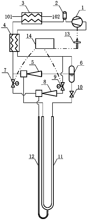
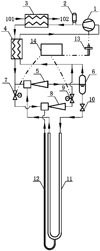
[0034] Such as figure 1 As shown, this embodiment discloses an oil return device for a direct expansion ground source heat pump system with double ejectors, including a compressor 1, an oil separator 2, a condenser / gas cooler 3, an intermediate heat exchanger 4, First injector 5, gas-liquid separator 6, first solenoid valve 7, second injector 8, second solenoid valve 9, throttle valve 10, downhole heat exchanger 11, oil return pipe 12, oil level sensor 13, A controller 14 , a low-temperature brine working fluid outlet 101 , and a high-temperature brine working fluid inlet 102 .

[0035] Wherein, the downhole heat exchanger 11 and the oil return pipe 12 are buried in the underground soil, and the rest of the compo...


PUM


Abstract

The invention relates to the technical field of ground-source heat pumps and discloses an oil return system of a straight expanding ground-source heat pump system with double injectors and an oil return method thereof. The oil return device of the system comprises a compressor, an oil separator, a condenser/gas cooler, an intermediate heat exchanger, a first injector, a gas-liquid separator, a first electromagnetic valve, a second injector, a second electromagnetic valve, a throttling valve, a downhole heat exchanger, an oil return pipe, an oil level sensor and a controller. By applying the injectors to the straight expanding ground-source heat pump system, a high pressure refrigerant working medium at the outlet of the intermediate heat exchanger in an oil return working condition is injected by the second injector to be collected in liquid state lubricating oil in a U-shaped bend of the oil return pipe. Under the circumstance of no external input power, the lubricating oil returns tothe compressor smoothly, so that the problem of oil return of the compressor of the straight expanding ground-source heat pump system in a heat supply working condition can be solved, and the throttling loss can be also reduce and the input power of the compressor is saved. The system is suitable for all refrigerant working media.

Description

technical field [0001] The invention relates to the technical field of ground source heat pumps, and more specifically relates to an oil return device and an oil return method of a direct expansion ground source heat pump system. Background technique [0002] In northern China, urban heating energy consumption in winter accounts for 40% of the national urban building energy consumption, which is the main component of building energy consumption. In terms of heating methods, central heating and combined heat and power generation are mainly used, and the fuel used in both is mainly coal. The coal-based heating method not only consumes a large amount of coal resources, but also causes serious environmental pollution. Therefore, it is particularly important to develop clean, efficient, and energy-saving renewable energy heating technologies. As a new type of inter-seasonal energy storage and utilization technology for geological bodies, the direct expansion ground source heat ...

Claims


Application Information

Patent Timeline
IPC IPC(8): F25B27/00F25B31/00F25B41/04F25B41/06F25B49/02F25B41/20F25B41/30
CPCF25B27/00F25B31/004F25B49/02F25B2313/002F25B2700/03F25B2341/0015F25B2341/0016F25B2600/25F25B41/20F25B41/30
Inventor 许文杰李敏霞
Owner TIANJIN UNIV
Why Eureka
Try Eureka