Dish-washing machine

A technology for dishwashers and cabinets, which is applied to tableware washing machines/rinsing machines, tableware washing machines/rinsing and rinsing machine parts, cleaning equipment, etc., and can solve problems such as poor cleaning effect and inability to be sprayed , to achieve the effect of reducing the area that cannot be irradiated, reducing the thickness, and reducing the space used

Active Publication Date: 2018-09-28
台州艾斐科技有限公司
View PDF6 Cites 1 Cited by
  • Summary
  • Abstract
  • Description
  • Claims
  • Application Information

AI Technical Summary

Problems solved by technology

[0005] The object of the present invention is to provide a dishwasher, which solves the problem that the existing dishwasher sprayer is arranged at the bottom, and some areas cannot be sprayed, resulting in poor cleaning effect.

Method used


Image

  • Dish-washing machine
  • Dish-washing machine
  • Dish-washing machine

Examples


Embodiment 1

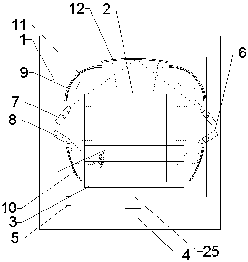
[0032] Such as figure 1 , figure 2 , image 3 As shown, a kind of dishwasher provided by the present invention includes: a casing 1 and a dish rack 2, the dishwasher also includes a base 3, the bowl rack is placed on the base, and the base is driven by a fixed rotating shaft 25 Connect the second drive motor 4 located at the bottom of the case. The bottom of the casing is provided with an outlet pipe 5 . The water outlet pipe is located on the left side of the casing.

[0033] The left and right inner walls of the casing are provided with a pair of oppositely arranged water spray pipe groups 6, and the water spray pipe groups include a first water spray pipe 7 on the upper part and a second water spray pipe 8 on the lower part. The central axis of a water spray pipe is 45° to the vertical line, and the central axis of the second water spray pipe is -45° to the vertical line; the first water spray pipe and the second water spray pipe of the present invention are configured...

Embodiment 2

[0040] A kind of dishwasher provided by the present invention comprises: a casing and a dish rack, and a pair of relatively arranged water spray pipe groups are arranged on the left and right inner walls of the casing, and the water spray pipe groups include a first spray nozzle located on the upper part. The water pipe and the second water spray pipe located at the bottom, the central axis of the first water spray pipe is 45° to the vertical line, and the central axis of the second water spray pipe is -45° to the vertical line;

[0041] A pair of upper side ultraviolet lamps and a pair of lower side ultraviolet lamps are also fixed in the casing, the pair of upper side ultraviolet lamps are respectively located at the left and right corners of the upper part of the bowl rack, and the pair of lower side ultraviolet lamps are respectively located at the bowl rack. At the left and right end corners of the upper part of the frame, the surface of the upper ultraviolet light fixture...


PUM


Abstract

The invention provides a dish-washing machine, which comprises a machine shell and a dish rack, wherein a pair of water spraying pipe groups, which are oppositely arranged, are each arranged on the inner walls of the left and right sides of the machine shell; each water spraying pipe group comprises a first water spraying pipe which is arranged at the upper side and a second water spraying pipe which is arranged at the lower side; the central axis of each first water spraying pipe forms an angle of 45 degrees with a perpendicular line; and the central axis of each second water spraying pipe forms an angle of minus 45 degrees with the perpendicular line. A pair of upper side ultraviolet lamps and a pair of lower side ultraviolet lamps are additionally fixed to the interior of the machine shell. According to the dish-washing machine provided by the invention, a water flow can be reflected on the basis of the skillful use of the surfaces of the ultraviolet lamps which follow directional configuration, so that areas, which cannot be irradiated, are reduced, and a spraying effect can be improved; a space occupied by the interior of the entire machine shell is diminished; and the thickness of the wall of the machine shell is reduced.

Description

technical field [0001] The invention relates to the field of household appliances, in particular to a dishwasher. Background technique [0002] Dishwashers are currently the most popular household appliances among consumers. The existing dishwasher has a rotating water flow distributor at the bottom of the tank; however, due to the rotary type, the water flow distribution is circular, and in actual products, due to the need for maximum use of space, the tank body is mostly square Or a square. Therefore, many places cannot be sprayed. [0003] For example: the existing application number is the patent document CN201510742463.X, which discloses the patent document "A Dishwasher Sprayer and Dishwasher Equipped with the Above-mentioned Sprayer and Its Control Method", and discloses a dishwashing machine with For the machine, the sprinkler is set at the bottom, and some areas cannot be sprayed, resulting in the defect of poor cleaning effect. Contents of the invention [00...

Claims


Application Information

Patent Timeline
IPC IPC(8): A47L15/16A47L15/42
Inventor 古嵘古乐怡熊婷
Owner 台州艾斐科技有限公司
Why Eureka
Try Eureka