Chip collecting device of chip discharging machine

A chip removal machine and chip collection technology, which is applied in the direction of metal processing machinery parts, maintenance and safety accessories, metal processing equipment, etc., can solve the problem of affecting the efficiency and progress of continuous production and processing, metal chips occupy a large work site, and collect box space Limited problems, to achieve the effect of improving the efficiency of mechanical chip removal, improving space utilization, and convenient transportation and movement

Inactive Publication Date: 2018-09-28
马鞍山市盟盛机械制造有限公司
View PDF6 Cites 2 Cited by
  • Summary
  • Abstract
  • Description
  • Claims
  • Application Information

AI Technical Summary

Problems solved by technology

[0003] Traditional mechanical processing and manufacturing companies usually adopt two methods for metal chips: one is to directly pile up metal chips near the metal chip machine tool, and after a certain period of time, the manufacturer responsible for recycling metal chips will send a car to collect and transport them. Go, under such circumstances, metal chips often occupy a large amount of work space, and there are not small safety hazards, and metal chips with cooling lubricants will also pollute the surrounding environment
The other is to use the chip conveyor to discharge metal and other waste chips mechanically, and place the corresponding collection box at the discharge port of the chip conveyor to collect and process the waste chips, which greatly slows down the machining process. The labor workload of the factory's traditional waste disposal, but

Method used


Image

  • Chip collecting device of chip discharging machine
  • Chip collecting device of chip discharging machine
  • Chip collecting device of chip discharging machine

Examples


Embodiment Construction

[0023] The following will clearly and completely describe the technical solutions in the embodiments of the present invention with reference to the accompanying drawings in the embodiments of the present invention. Obviously, the described embodiments are only some, not all, embodiments of the present invention. Based on the embodiments of the present invention, all other embodiments obtained by persons of ordinary skill in the art without making creative efforts belong to the protection scope of the present invention.

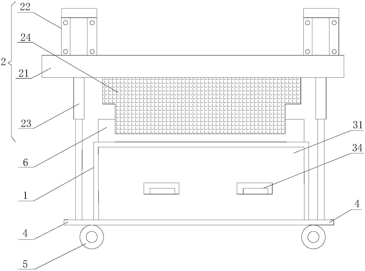
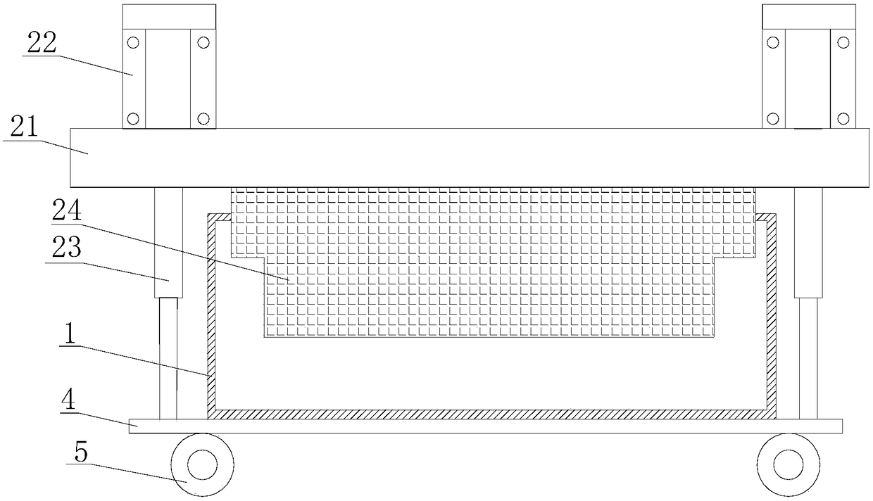
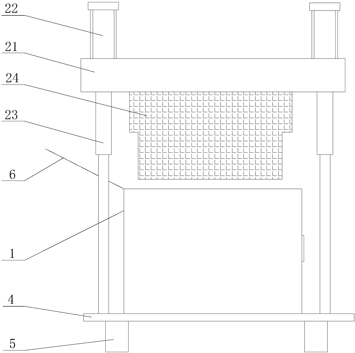
[0024] see Figure 1-6 , in the embodiment of the present invention: a chip collection device of a chip removal machine, including a chip collection box 1, a pressing mechanism 2 and a discharge mechanism 3, and the discharge mechanism 3 includes an inner layer chip collection box 31 and a telescopic shaft 32; One end of the telescopic shaft 32 is fixedly welded on the inner wall of the dust collection box 1, and the other end of the telescopic shaft 32 is rot...


PUM


Abstract

The invention discloses a chip collecting device of a chip discharging machine. The chip collecting device of the chip discharging machine comprises a chip collecting box, a material pressing mechanism and a material pouring mechanism. The material pouring mechanism comprises an inner chip collection box body and telescopic shafts, wherein the inner chip collection box is embedded into a cavity ofthe chip collection box through sliding grooves on the two sides, and the other face of the inner chip collection box body is connected into the chip collection box through the telescopic shafts. Thechip collection box body is fixedly welded to the base. The upper end face of the base is provided with a material pressing mechanism. The material pressing mechanism comprises a material pressing cover plate, lifting air cylinders, air cylinder push rods and a material pressing lead block. The material pressing cover plate is driven by the lifting air cylinders and move up and down along the aircylinder push rods. According to the chip collecting device of the chip discharging machine, the material pressing mechanism is arranged, after compression is conducted through the material pressinglead block, mechanical waste is pressed together, so that the space utilization rate in the inner chip collection box body is greatly improved, the waste collection time of the machine is g prolonged,and the chip discharging efficiency of the machine is improved; in addition, the material pouring mechanism is arranged, so that materials in the inner chip collection box body can be pulled out andoverturned and poured out by the telescopic shafts, in the whole process, time and effort are saved, and operation is easy and convenient.

Description

technical field [0001] The invention relates to the technical field of chip removal equipment, in particular to a chip collection device of the chip removal machine. Background technique [0002] Machining and manufacturing companies usually produce a large amount of metal swarf when processing parts through metal cutting. At present, traditional mechanical processing and manufacturing enterprises, especially those that use a large number of metal cutting machine tools, usually do not adopt effective containers to collect, store, and transfer metal chips. [0003] Traditional mechanical processing and manufacturing companies usually adopt two methods for metal chips: one is to directly pile up metal chips near the metal chip machine tool, and after a certain period of time, the manufacturer responsible for recycling metal chips will send a car to collect and transport them. Go, under such circumstances, metal chips often occupy a large amount of work space, and there are no...

Claims


Application Information

Patent Timeline
IPC IPC(8): B23Q11/00
CPCB23Q11/0042
Inventor 陈刚黄志刚贺电辉
Owner 马鞍山市盟盛机械制造有限公司
Why Eureka
Try Eureka