Method of preparing base material and base material

A substrate and substrate technology, applied in the field of 3D printing, can solve the problems of waste, long printing process and cutting process, unable to reflect the technical advantages of 3D printing technology in saving time and material, and saving printing materials and printing time. Effect

Pending Publication Date: 2018-09-28
TSC LASER TECH DEV BEIJING CO LTD
View PDF6 Cites 4 Cited by
  • Summary
  • Abstract
  • Description
  • Claims
  • Application Information

AI Technical Summary

Problems solved by technology

The physical support and parts are obtained through printing at the same time. The material of the physical support is the same as that of the parts, which is very wasteful, and the printing process and cutting process are long, which cannot reflect the time-saving and material-saving technical advantages of 3D printing technology.

Method used


Image

  • Method of preparing base material and base material

Examples


Embodiment 1

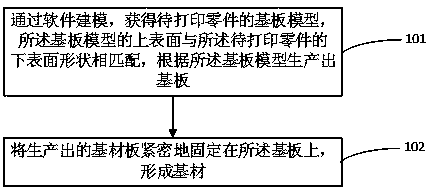
[0019] Such as figure 1 As shown, the embodiment of the present invention discloses a method for preparing a substrate, comprising:

[0020] 101. Obtain a substrate model of a part to be printed through software modeling, the upper surface of the substrate model matches the shape of the lower surface of the part to be printed, and produce a substrate according to the substrate model.

[0021] In this embodiment, through software modeling, the software adopts CATIA V5, and the part model to be printed is projected from top to bottom, and the lower surface, horizontal projection surface, side elevation and front elevation of the part model to be printed are enclosed The substrate model of the part to be printed is obtained.

[0022] In this embodiment, the lower surface of the part to be printed is a curved surface, and the upper surface of the substrate is a curved surface matching the part to be printed.

[0023] More specifically, if the part to be printed is a spherical pa...

Embodiment 2

[0030] The embodiment of the present invention discloses a base material, which includes a base plate and a base plate tightly fixed to the base plate, and the upper surface of the base plate matches the shape of the lower surface of a part to be printed.

[0031] In this embodiment, the lower surface of the part to be printed is a curved surface, and the upper surface of the substrate is a curved surface matching the part to be printed.

[0032] In this embodiment, the base plate and the upper surface of the base plate are fixed by rivets, and the side elevation and the front elevation of the base plate and the base plate are fixed by steel nails.

[0033] In this embodiment, the material of the base plate is the same as or similar to that of the part to be printed, and the material of the substrate is steel or cast iron.

[0034] It can be seen that the upper surface of the base material provided by this embodiment has a shape that matches the lower surface of the part. When...


PUM

PropertyMeasurementUnit
thicknessaaaaaaaaaa

Abstract

The invention discloses a method of preparing base material and a base material. The method of preparing the base material includes the steps that through software modeling, a base plate model of a to-be-printed part is obtained; the shape of the upper surface of the base plate model is matched with the shape of the lower surface of the to-be-printed part, and a base plate is produced according tothe base plate model; and a produced base material plate is tightly fixed to the base plate to form the base material. According to he base material obtained through the method, the shape of the upper surface of the base material is matched with the shape of the lower surface of the to-be-printed part; when the parts are printed, the needed parts can be directly printed without printing a solid support and printing time is saved and printing materials are saved.

Description

technical field [0001] The invention relates to the field of 3D printing, in particular to a method for preparing a base material and a base material. Background technique [0002] At present, in 3D printing technology, that is, in the preparatory process of additive manufacturing, the method of solid support is often used when designing the machining allowance for parts whose lower surface is non-planar. The base material used in this method is usually flat. When printing a part with a non-planar lower surface, it is necessary to print out the solid support layer by layer on the plane of the base material, starting from the bottom, according to the layered data of the part model. And parts whose lower surface is non-planar, cut the solid support after printing to obtain the part. The physical support and parts are obtained through printing at the same time. The material of the physical support is the same as that of the parts, which is very wasteful, and the printing proce...

Claims


Application Information

Patent Timeline
Patent Type & Authority Applications(China)
IPC IPC(8): B29C64/386B29C64/245B29C64/10B22F3/00B33Y50/00B33Y10/00B33Y30/00B33Y80/00B22F10/00B22F12/30
CPCB22F3/00B29C64/10B29C64/245B29C64/386B33Y10/00B33Y30/00B33Y50/00B33Y80/00
Inventor 李广生王辰辰李澄其他发明人请求不公开姓名
Owner TSC LASER TECH DEV BEIJING CO LTD
Why Eureka
Try Eureka