
Oil pressure hand braking control mechanism used for automobile

A control mechanism and hand brake technology, applied in the direction of brakes, manual starting devices, braking action starting devices, etc., can solve the problems of increased cost, short life, and laborious braking of the driver, and achieve simple structure, long life, small size effect

Pending Publication Date: 2018-09-28
LUOYANG YELLOW RIVER FLEXIBLE SHAFT CONTROLLER
View PDF9 Cites 0 Cited by
  • Summary
  • Abstract
  • Description
  • Claims
  • Application Information

AI Technical Summary

Problems solved by technology

[0002] The hand brake control mechanisms currently used in the market are all mechanical brakes or pneumatic brakes. During the manipulation process, there are many unfavorable factors in the use process; the mechanical brake mechanism often has too much manipulation force during use, and the driving The driver’s braking is laborious, or the braking effect is not good, causing accidents such as vehicle landslides; if the brake handle is lengthened, it will occupy too much space inside the cab, and the handle swing is too large during braking, causing the driver to operate inconveniently; The force is large, the mechanism and accessories are easily damaged, the life is short, and there are potential safety hazards; existing vehicles generally use oil pressure mechanisms to control steering and foot braking. gas and accessory equipment, the cost increases; and the whole set of equipment is bulky, posing safety hazards

Method used


Image

  • Oil pressure hand braking control mechanism used for automobile
  • Oil pressure hand braking control mechanism used for automobile

Examples


Embodiment Construction

[0014] The present invention is described in conjunction with the accompanying drawings and specific implementation, but does not constitute a limitation to the invention:

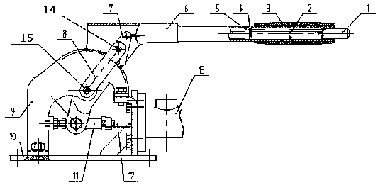
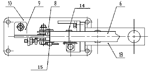
[0015] like figure 1 and figure 2 Shown, a kind of oil pressure hand brake control mechanism for automobile, described automobile oil pressure hand brake control mechanism has brake handle 6, and described brake handle 6 has the horizontal bar of horizontal arrangement; The front end of the handle 6 is sleeved, and the handle cover 3 is on the brake handle 6 to play an anti-slip effect; the rear end of the horizontal bar described in the brake handle 6 is inclined downward to form a support rod for the brake handle; The lower end of the support rod is hinged with one end of the centering joint draw ring 11, forming the structure that the brake handle 6 can rotate around the hinge point of the brake handle and the centering joint draw ring under the pull of the hand; The other end of the joint pull ring ...


PUM


Abstract

The invention belongs to the technical field of braking control used for automobiles and provides an oil pressure hand braking control mechanism used for an automobile. The provided oil pressure handbraking control mechanism used for the automobile is provided with a braking handle, and the braking handle is provided with a horizontally-arranged horizontal rod; the rear end of the horizontal rodinclines obliquely downwards to form a supporting rod of the braking handle; the lower end of the supporting rod is hinged to one end of an aligning knuckle pull ring; the other end of the aligning knuckle pull ring makes contact with a valve element of a braking oil cylinder through an ejector rod; a push rod is arranged in the center of the braking handle; the front end of the push rod extends out of the braking handle and is connected with a button; the rear end of the push rod is connected with a pawl; the push rod is sleeved with a spacer bush; a compression spring is arranged between thespacer bush and the button; reinforcing plates are installed on the two sides of the pawl and the two sides of a ratchet wheel plate; and one end of each of the two reinforcing plates is hinged to the pawl through a hinge pin I, and the other end of each of the two reinforcing plates is hinged to the ratchet wheel plate through a hinge pin II. Through cooperation of the pawl, the ratchet wheel plate and the braking oil cylinder, manual braking is achieved, and the mechanism has the beneficial effects of being simple in structure, long in service life and small in size.

Description

technical field [0001] The invention belongs to the technical field of brake control for automobiles, and mainly relates to a hydraulic hand brake control mechanism for automobiles. Background technique [0002] The hand brake control mechanisms currently used in the market are all mechanical brakes or pneumatic brakes. During the manipulation process, there are many unfavorable factors in the use process; the mechanical brake mechanism often has too much manipulation force during use, and the driving The driver’s braking is laborious, or the braking effect is not good, causing accidents such as vehicle landslides; if the brake handle is lengthened, it will occupy too much space inside the cab, and the handle swing is too large during braking, causing the driver to operate inconveniently; The force is large, the mechanism and accessories are easily damaged, the life is short, and there are potential safety hazards; existing vehicles generally use oil pressure mechanisms to c...

Claims


Application Information

Patent Timeline
Patent Type & Authority Applications(China)
IPC IPC(8): B60T7/10
CPCB60T7/101
Inventor 庞媛媛杜万庆杜庆丽杨钧
Owner LUOYANG YELLOW RIVER FLEXIBLE SHAFT CONTROLLER
Learn More