Three-joint bionic mechanical leg with autonomous hydraulic distribution power

A bionic mechanical leg and hydraulic power system technology, applied in the field of bionic robots, can solve the problems of inconvenient disassembly and maintenance, small joint torque, low charging efficiency, etc., and achieve the effect of convenient debugging and operation, large joint torque and simple structure

Pending Publication Date: 2018-09-28
长沙紫宸科技开发有限公司
View PDF14 Cites 1 Cited by
  • Summary
  • Abstract
  • Description
  • Claims
  • Application Information

AI Technical Summary

Problems solved by technology

[0007] The technical problem to be solved by the present invention is to overcome the disadvantages of inconvenient disassembly and maintenance, small joint torque, complex structure and low charging efficiency in the above-mentioned prior art, and provide a convenient installation and disassembly, large joint torque, and relatively small structure. Simple, reliable operation, high charging efficiency, three-joint bionic mechanical leg with autonomous hydraulic power distribution

Method used


Image

  • Three-joint bionic mechanical leg with autonomous hydraulic distribution power
  • Three-joint bionic mechanical leg with autonomous hydraulic distribution power
  • Three-joint bionic mechanical leg with autonomous hydraulic distribution power

Examples


Embodiment 1

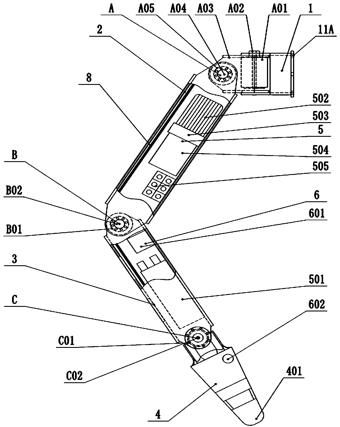
[0032] refer to figure 1 , figure 2 , the three-joint bionic mechanical leg with autonomous hydraulic distribution power in this embodiment has four degrees of freedom, mainly including connecting frame 1, three-dimensional joint A, thigh 2, two-dimensional joint B, lower leg 3, two-dimensional joint C, foot 4. Hydraulic power system 5, control device 6; the three-dimensional joint A is fixed on the connecting frame 1 and connected to the thigh 2, the thigh 2 is connected to the lower leg 3 through the two-dimensional joint B, and the lower leg 3 is connected to the foot 4 through the two-dimensional joint C , the hydraulic power system 5 is fixed in the cavity of the leg body of the thigh 2 and the calf 3, and is respectively connected with the hydraulic interfaces of the three-dimensional joint A, the two-dimensional joint B, and the two-dimensional joint C through hydraulic pipelines, and the control device 6 is fixed on the calf 3, the control device 6 is electrically co...

Embodiment 2

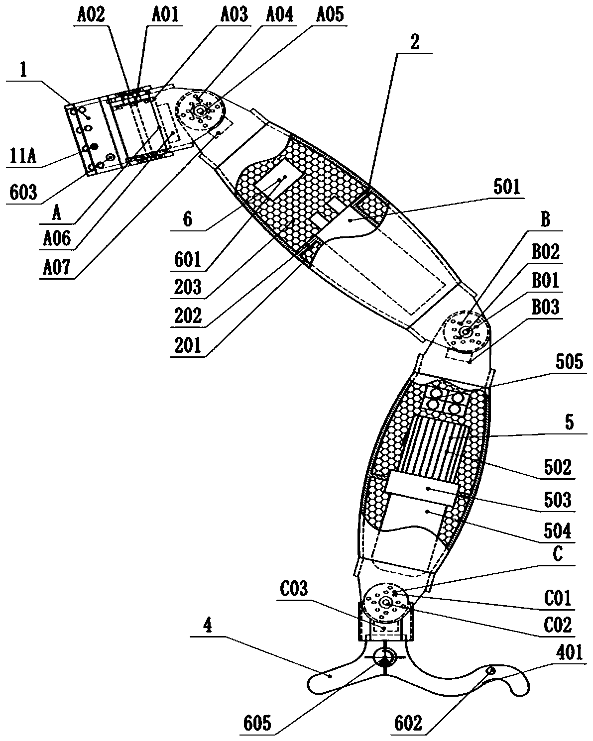
[0041] refer to image 3 , Figure 4 , the three-joint bionic mechanical leg with autonomous hydraulic distribution power in this embodiment has four degrees of freedom, mainly including connecting frame 1, three-dimensional joint A, thigh 2, two-dimensional joint B, lower leg 3, two-dimensional joint C, foot 4. Hydraulic power system 5, control device 6; the three-dimensional joint A is fixed on the connecting frame 1 and connected to the thigh 2, the thigh 2 is connected to the lower leg 3 through the two-dimensional joint B, and the lower leg 3 is connected to the foot 4 through the two-dimensional joint C , the hydraulic power system 5 is fixed in the femur cavities of the thigh 2 and the calf 3, and is respectively connected with the hydraulic interfaces of the three-dimensional joint A, the two-dimensional joint B, and the two-dimensional joint C through hydraulic pipelines, and the control device 6 is fixed on the connecting frame 1 In the cavities of the thigh 2 and t...

Embodiment 3

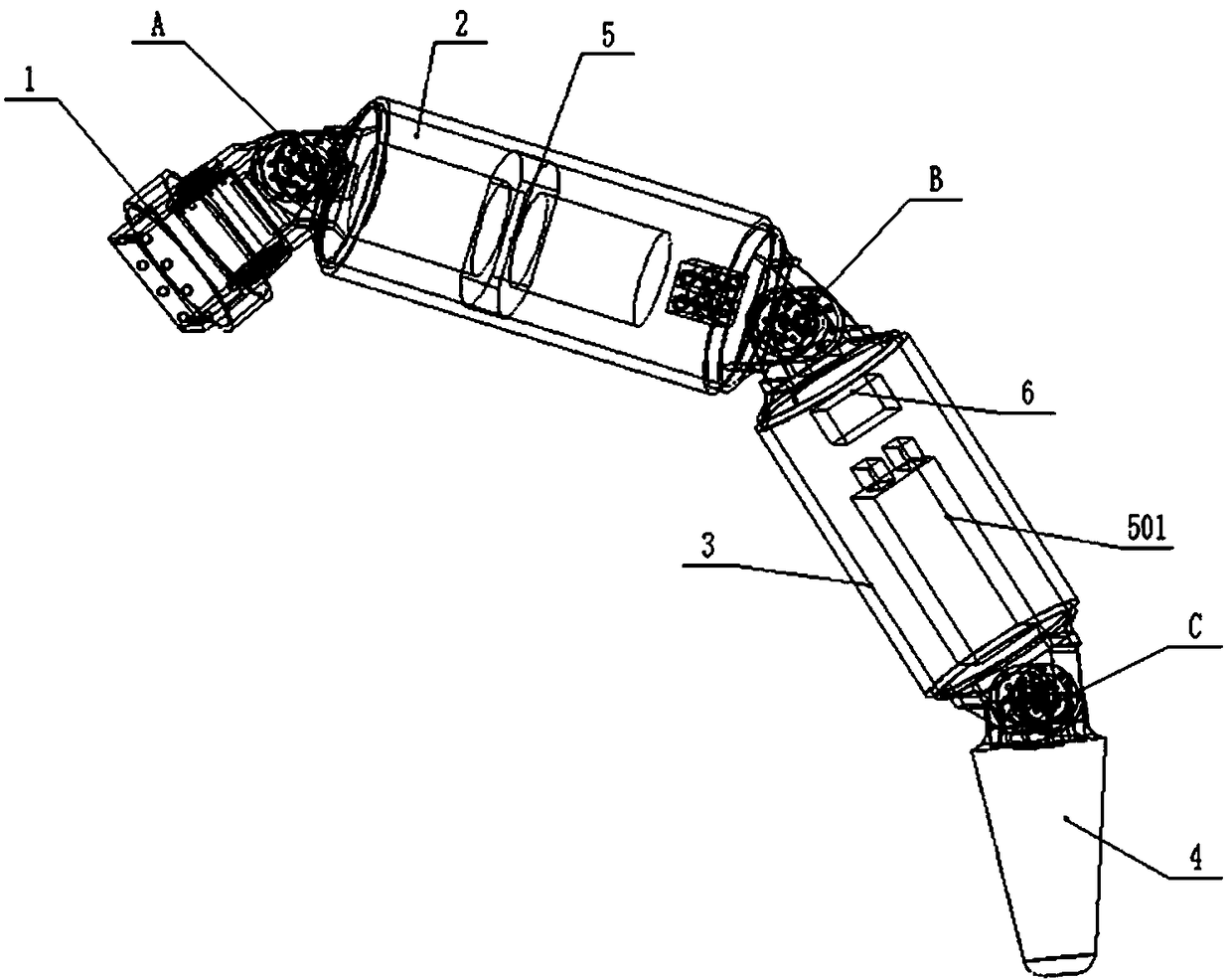
[0047] refer to Figure 5 , Figure 6 , the three-joint bionic mechanical leg with autonomous hydraulic distribution power in this embodiment has four degrees of freedom, mainly including connecting frame 1, three-dimensional joint A, thigh 2, two-dimensional joint B, lower leg 3, two-dimensional joint C, foot 4. Hydraulic power system 5, control device 6; the three-dimensional joint A is fixed on the connecting frame 1 and connected to the thigh 2, the thigh 2 is connected to the lower leg 3 through the two-dimensional joint B, and the lower leg 3 is connected to the foot 4 through the two-dimensional joint C , the hydraulic power system 5 is fixed in the femur cavities of the thigh 2 and the calf 3, and is respectively connected with the hydraulic interfaces of the three-dimensional joint A, the two-dimensional joint B, and the two-dimensional joint C through hydraulic pipelines, and the control device 6 is fixed on the connecting frame 1 In the cavities of the lower leg 3 ...


PUM


Abstract

The invention discloses a three-joint bionic mechanical leg with autonomous hydraulic distribution power. The three-joint bionic mechanical leg includes a thigh, a calf, a foot, a connecting frame, ahydraulic power system and a control device, and the connecting frame, the thigh, the calf and the foot are connected through joints in sequence. The bionic mechanical leg is fixedly connected or disassembled with a bionic robot through the connecting frame, and the hydraulic power system is arranged on the thigh and / or the calf and / or the foot. The control device is arranged on the thigh and / or the calf and / or the connecting frame and / or the foot. The three-joint bionic mechanical leg with the autonomous hydraulic distribution power can be quickly and fixedly connected and disassembled with the bionic robot, the torque is larger, and the operating control is simpler.

Description

technical field [0001] The invention relates to a bionic robot, in particular to a three-joint bionic mechanical leg with autonomous hydraulic distribution power of the bionic robot. Background technique [0002] Compared with wheeled and tracked mobile robots, bionic robots only need to touch the ground at discrete points when moving, can cross larger obstacles, and have stronger adaptability to complex terrain, and the legs of bionic robots can have multiple degrees of freedom. The movement flexibility and performance are greatly enhanced, and the body balance can be maintained by adjusting the angle of the supporting legs and the foot landing position, which is not easy to tip over and has high stability. In the future, bionic robots will have broader application prospects in life services, pipeline maintenance, flood fighting and disaster relief, film and television performances, security and military affairs. [0003] For the key component of the bionic robot—the bioni...

Claims


Application Information

Patent Timeline
Patent Type & Authority Applications(China)
IPC IPC(8): B62D57/032H02J7/35F03G7/04
CPCH02J7/35F03G7/04B62D57/032
Inventor 尹小林韩建英
Owner 长沙紫宸科技开发有限公司
Why Eureka
Try Eureka