
In-tube paste recovery device

A recovery device and paste technology, which is applied in the field of paste recovery devices in pipes, can solve the problems of no paste collection or recovery equipment or devices in pipes, loss of paste, and inability to collect and utilize paste, achieving excellent recovery effects and easy The effect of simple operation and structure

Pending Publication Date: 2018-09-28
CHONGQING DENCARE CORP
View PDF0 Cites 1 Cited by
  • Summary
  • Abstract
  • Description
  • Claims
  • Application Information

AI Technical Summary

Problems solved by technology

[0002] At present, during the product line change and cleaning process of toothpaste production, the paste in the pipeline cannot be collected and used for direct cleaning for scrapping, resulting in unnecessary paste loss
Therefore, it is necessary to recycle the paste in the pipe during the production process, but in the prior art, there is no equipment or device that can collect or recycle the paste in the pipe

Method used


Image

  • In-tube paste recovery device
  • In-tube paste recovery device
  • In-tube paste recovery device

Examples


Embodiment 1

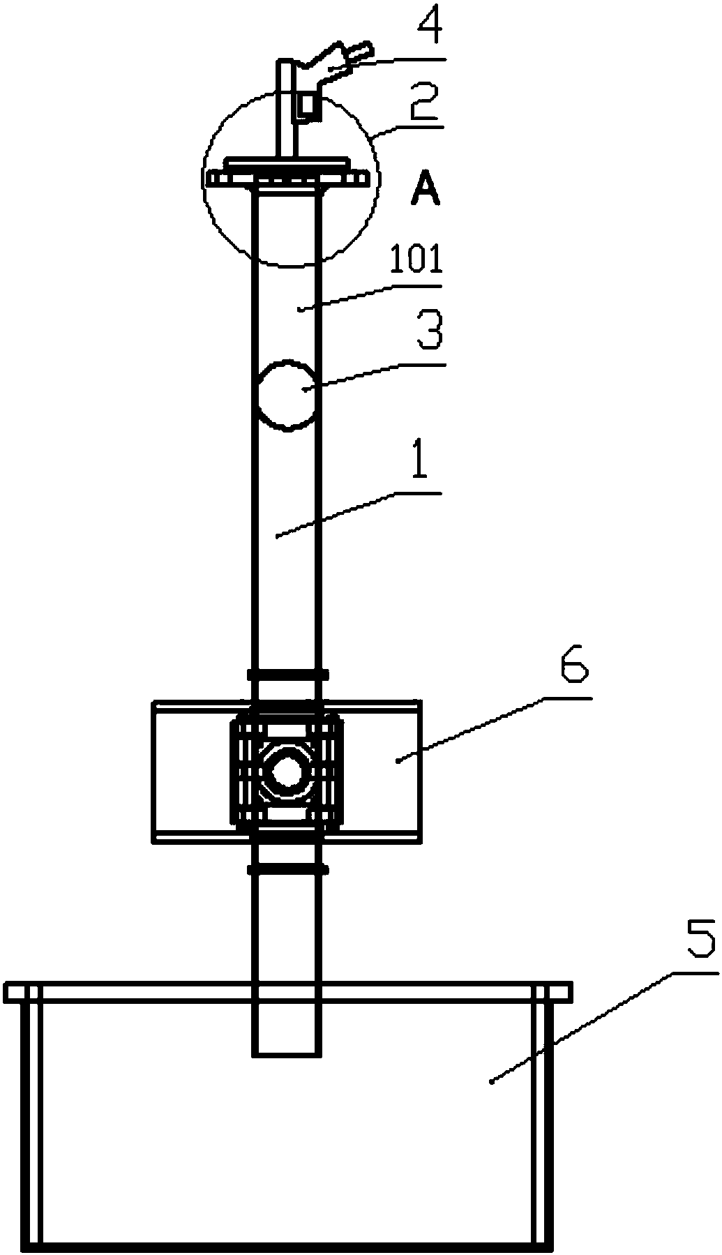
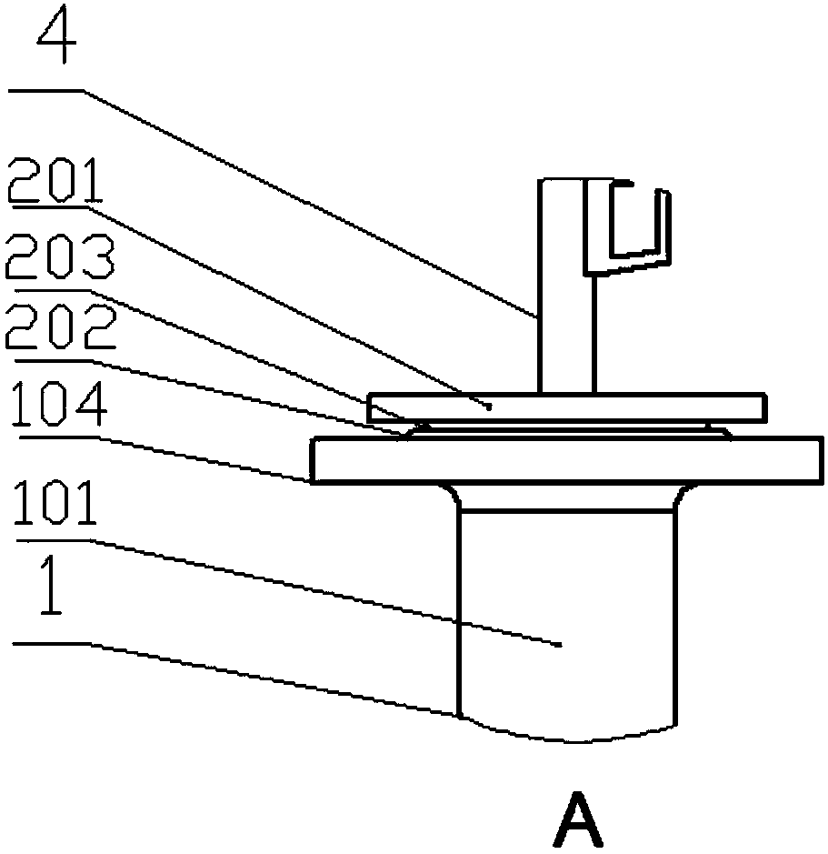
[0023] A kind of paste recovery device in the pipe, such as figure 1 As shown, it includes a pipeline 1 with a ball valve 6, a sealing structure 2 for sealing the pipeline 1 is provided at the pipeline inlet 101, and a flexible extruding part 3 is arranged in the pipeline 1, and the flexible extruding part 3 and the inner wall of the pipeline 1 are seamless. There is clearance fit, and a compressed air source is connected in the pipe section 101 located between the sealing structure 2 and the flexible extrusion part 3 .

[0024] Further, an air pressure gun 4 connected to the pipe section 101 is provided on the sealing structure 2, and the air pressure gun 4 is connected to a compressed air source, and compressed air is injected into the pipe section 101 through the air pressure gun 4 to realize the movement of the flexible extruding part 3. In this embodiment, the air pressure gun is a dust blowing gun.

[0025] Further, the flexible extruding part 3 is a silicone sphere, a ...

Embodiment 2

[0034] A kind of paste recovery device in the pipe, such as figure 1 As shown, it includes a pipeline 1 with a pneumatic ball valve, a sealing structure 2 for sealing the pipeline 1 is provided at the pipeline inlet 101, and a flexible extruding part 3 is arranged in the pipeline 1, and the flexible extruding part 3 and the inner wall of the pipeline 1 are seamless. There is clearance fit, and a compressed air source is connected in the pipe section 101 located between the sealing structure 2 and the flexible extrusion part 3 .

[0035] Further, an air pressure gun 4 connected to the pipe section 101 is provided on the sealing structure 2, and the air pressure gun 4 is connected to a compressed air source, and compressed air is injected into the pipe section 101 through the air pressure gun 4 to realize the movement of the flexible extruding part 3. In this embodiment, the air pressure gun 4 is a dust blowing gun.

[0036] Further, the flexible extruding part 3 is a silicone ...

Embodiment 3

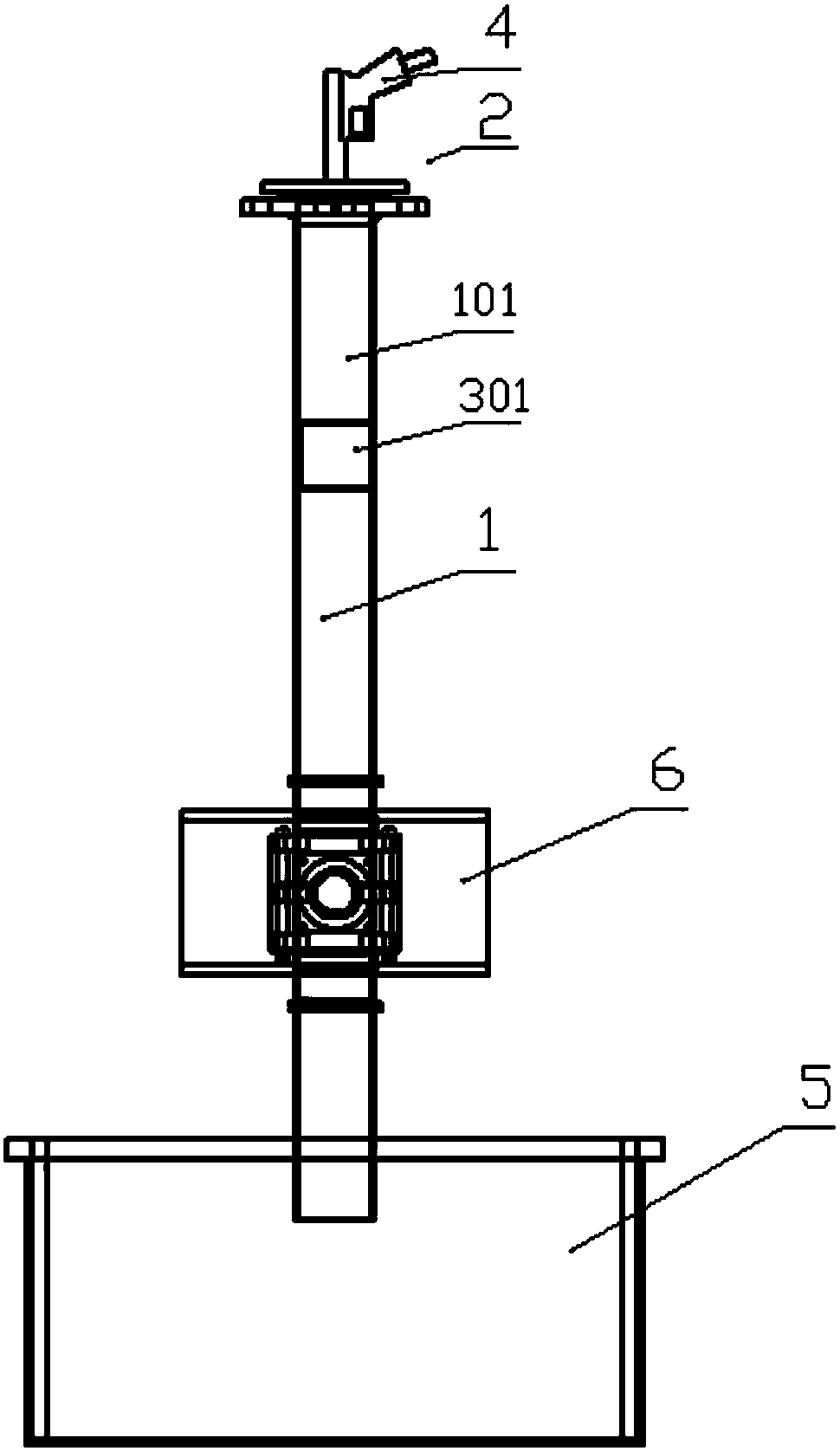
[0044] A kind of paste recovery device in the tube, with reference to embodiment 1 and image 3 . Among them, the flexible extruding part is a silicone cylinder that meets hygienic requirements, and the maximum outer diameter of the silicone cylinder is 0.5mm larger than the inner diameter of the pipe.


PUM


Abstract

The invention provides an in-tube paste recovery device. The in-tube paste recovery device comprises a tube. A sealing structure for tube sealing is arranged at a tube inlet. A flexible squeezing partis arranged in the tube and is in gapless fit with the inner wall of the tube. A compressed gas source communicates with the interior of a tube section located between the sealing structure and the flexible squeezing part. The in-tube paste recovery device has an excellent recovery effect on in-tube paste, especially on attached paste in the tube with certain viscosity, in the product line changing and cleaning processes of toothpaste production, by adopting the in-tube paste recovery device, in-tube toothpaste can be effectively recovered, recycling of in-tube paste is achieved, and the toothpaste production cost is greatly reduced.

Description

technical field [0001] The invention relates to toothpaste production equipment, in particular to an in-pipe paste recycling device. Background technique [0002] At present, during the product line change and cleaning process of toothpaste production, the paste in the pipeline cannot be collected and cleaned directly for scrapping, resulting in unnecessary loss of paste. Therefore, it is necessary to recycle the paste in the tube during the production process, but in the prior art, there is no equipment or device that can collect or recycle the paste in the tube. Contents of the invention [0003] The object of the present invention is to provide a device for recovering the paste in the tube, which can effectively recover the paste in the tube. [0004] In order to achieve the above object, the present invention adopts the following technical solutions. [0005] An in-pipe paste recovery device includes a pipe, a sealing structure for sealing the pipe is arranged at the...

Claims


Application Information

Patent Timeline
IPC IPC(8): B65B65/00B65B3/00
CPCB65B3/00B65B65/00
Inventor 彭佳华曹晴邓全富潘欢韩和平柴露琦邓嵘
Owner CHONGQING DENCARE CORP
Learn More