
Intelligent electronically controlled drainage method and device for steam drying cylinders

A steam dryer and hydrophobic technology, applied in the removal of liquid/gas/steam, textiles and papermaking, textile material treatment, etc., can solve the problems of increasing production and operating costs, increasing steam consumption, and easy accumulation of water in the drying cylinder. Achieve the effects of high hydrophobic measurement and control accuracy, improve steam utilization rate, and improve hydrophobic efficiency

Pending Publication Date: 2018-09-28
CHANGZHOU HONGDA INTELLIGENT EQUIP IND DEV RES INST CO LTD
View PDF5 Cites 0 Cited by
  • Summary
  • Abstract
  • Description
  • Claims
  • Application Information

AI Technical Summary

Problems solved by technology

[0006] The existing electronically controlled drainage methods and devices for steam dryers have the following two disadvantages in the working process: (1) When the steam temperature or pressure in the steam main pipe changes or the opening of the steam valve in the steam main pipe is artificially changed, the Neither the method nor the device can accurately perform drainage and accurately stop drainage, resulting in low thermal efficiency of the steam dryer, serious steam leakage, wasting a lot of energy, and greatly increasing steam consumption; (2) In the process of drying fabrics with water in the steam dryer In the middle, the steam lock cannot be released, and water is easy to accumulate in the drying cylinder, resulting in an increase in the weight of the drying cylinder, which has potential safety hazards. The water drainage efficiency and steam utilization rate are both low, which increases the production and operation costs.

Method used


Image

  • Intelligent electronically controlled drainage method and device for steam drying cylinders
  • Intelligent electronically controlled drainage method and device for steam drying cylinders
  • Intelligent electronically controlled drainage method and device for steam drying cylinders

Examples


Embodiment Construction

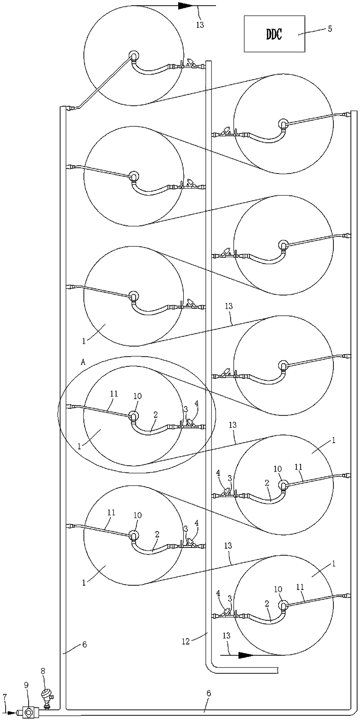
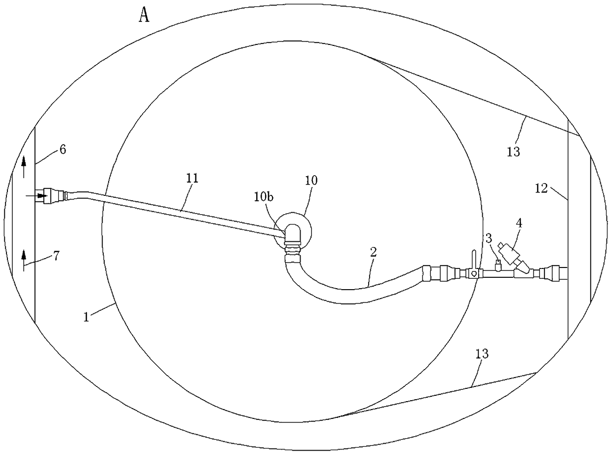
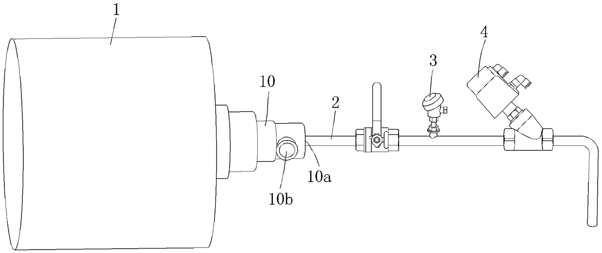
[0025] See Figure 1 to Figure 3 Shown is an intelligent electronically controlled drainage method for steam drying drums. The method uses steam 7 to be fed into the steam drying drum 1 through the steam main pipe 6, and the condensed water in the steam drying drum 1 is pushed out through the drain pipe 2 and the control valve 4 When the temperature in the pipe of the drain pipe 2 is equal to the product of the steam temperature in the steam main pipe 6 and the temperature coefficient K plus the return difference temperature △T is true, the control valve 4 is closed to stop the drain; When the temperature in the circuit is equal to the product of the steam temperature in the steam manifold 6 and the temperature coefficient K, the control valve 4 is opened to perform drainage; where 0°C<△T≤6°C, 0.6≤K≤0.9.

[0026] As a preferred embodiment of the above method, the value range of the hysteresis temperature ΔT is 2 to 5° C., and the value range of the temperature coefficient K is 0....


PUM


Abstract

The invention discloses am intelligent electronically controlled drainage method and device for steam drying cylinders. According to the drainage method, steam is introduced into the steam drying cylinders through a steam main pipe to accelerate discharge of condensed water in the steam drying cylinders to the outside. When it is true that the temperature in drainage pipes is equal to the sum of areturn difference temperature value delta T and a product of the steam temperature in the steam main pipe and a temperature coefficient K, control valves are switched off, and drainage is stopped; when it is true that the temperature in the drainage pipes is equal to the product of the steam temperature in the steam main pipe and the temperature coefficient K, the control valves are switched on,and drainage is conducted, wherein delta T is greater than 0 DEG C and less than or equal to 6 DEG C, and K is greater than or equal to 0.6 and less than or equal to 0.9. The drainage device comprisesthe steam drying cylinders, the drainage pipes, first temperature sensors, the control valves, an electric controller, the steam main pipe and a second temperature sensor or a steam pressure sensor which is installed on the steam main pipe and used for detecting the steam temperature or pressure in the steam main pipe. Drainage and stopping of drainage can be accurately performed, the thermal efficiency is improved, and the steam consumption amount is greatly decreased.

Description

Technical field [0001] The invention relates to an electrically controlled hydrophobic method and a hydrophobic device for a steam dryer, and belongs to the technical field of textile dyeing and finishing processes and equipment. Background technique [0002] Textile printing and dyeing enterprises use a large number of steam dryers to dry water-laden fabrics, and the condensed water in the steam dryer affects the heat exchange efficiency. It needs to be discharged in time to improve the thermal efficiency of the steam dryer, thereby saving steam and reducing energy consumption. [0003] The existing electronically controlled drainage device for steam drying drums includes a steam drying drum, a rotary joint, a drainage pipe connected to the inner cavity of the steam drying drum through the drainage port of the rotary joint, and is installed on the drainage pipe pipeline and used to detect the drainage pipe pipeline A temperature transmitter for internal temperature, a control valv...

Claims


Application Information

Patent Timeline
Patent Type & Authority Applications(China)
IPC IPC(8): D06B15/00
CPCD06B15/00
Inventor 顾金华
Owner CHANGZHOU HONGDA INTELLIGENT EQUIP IND DEV RES INST CO LTD
Learn More