Replaceable pre-embedded anchoring channel and mounting method thereof
What is AI technical title?
AI technical title is built by Patsnap AI team. It summarizes the technical point description of the patent document.
A channel and anchoring technology, which is applied in tunnels, tunnel linings, mining equipment, etc., can solve the problems of inestimable steel corrosion and large area, and achieve the effect of meeting the needs of structural design, reducing impact, and facilitating replacement
Pending Publication Date: 2018-09-28
ZHEJIANG HAOTE ENERGY SAVING SYST ENG CO LTD
View PDF8 Cites 1 Cited by
Summary
Abstract
Description
Claims
Application Information
AI Technical Summary
This helps you quickly interpret patents by identifying the three key elements:
Problems solved by technology
Method used
Benefits of technology
Problems solved by technology
In addition, the exposed area of the pre-buried channel is relatively large, and the degree of corrosion of the steel cannot be estimated, so the channel needs to be replaced to meet the use requirements
Method used
Image
Click on the blue label to locate the original text in one second.
Reading with bidirectional positioning of images and text.
Examples
Embodiment 1
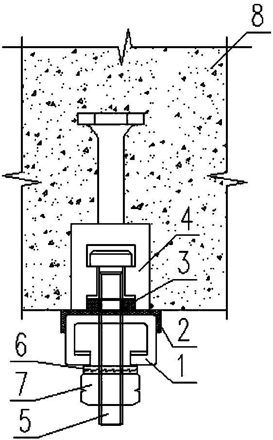
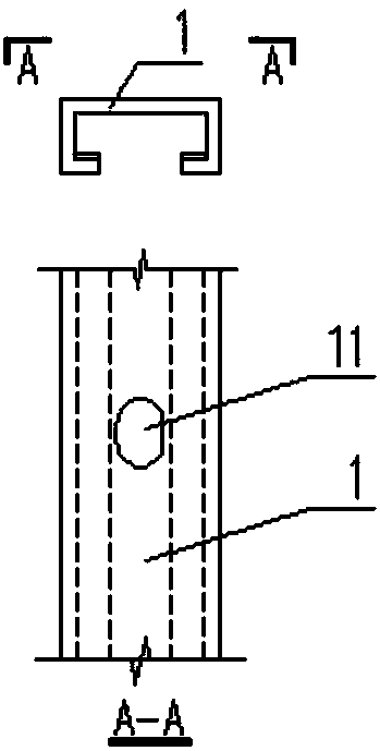
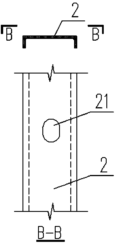
[0029] Embodiment 1: as figure 1 , figure 2 , image 3 , Figure 4 , Figure 5 , Image 6 , Figure 7 , Figure 8 , Figure 9 , Figure 10 , Figure 11 with Figure 12 As shown, a replaceable pre-embedded anchor channel, including channel 1, resin gasket 2, compression ring 3, anchor 4, T-bolt 5, anti-falling gasket 6, anti-falling nut 7 and Concrete segment 8. Described channel is hollow and the quadrilateral of opening is arranged at the bottom, on channel, open oblong hole 11 according to design requirement (see figure 2 ), resin gasket 2 (see image 3 ) is processed into a U-shape just to be buckled on the outside of the channel, and an oblong hole 21 is provided at the corresponding position of the oblong hole in the channel, adding a resin gasket 3 between the channel and the segment can reduce the influence of the channel on the concrete segment, thereby Protect the concrete segment; the compression ring 3 includes three parts: the ring body 31, the wrenc...
Embodiment 2
[0031] Embodiment 2: An installation method of a replaceable pre-embedded anchor channel includes the following steps:
[0032] Step 1: Select suitable anchors, compression rings and resin gaskets according to the channel and T-bolt specifications;
[0033] Step 2: According to the design requirements, install the anchors at a certain distance and embed them in the concrete segments;
[0034] Step 3: Open corresponding long round holes on the channel and resin gasket according to the corresponding spacing;
[0035] Step 4: Install T-bolts on the installed segment first, and fix it in the upper notch with a compression ring;
[0036] Step 5: Install the channel on the outside of the segment through T-bolts, and then fix it with anti-falling gaskets and anti-falling nuts;
[0037] Step 6: When replacing the channel, loosen the anti-falling nut, remove the channel for replacement, and check whether the T-bolt needs to be replaced.
PUM
Abstract
The invention discloses a replaceable pre-embedded anchoring channel and a mounting method thereof. A channel body is a hollow quadrilateral with an opening formed in the bottom. Long round holes areformed in the opposite positions of the channel body and a resin gasket correspondingly, a compression ring piece is additionally arranged between the channel body and a segment, a compression ring comprises a ring body, spanner holes and an inner thread, and a T-shaped bolt is fixed to an anchoring part through the compression ring with the inner thread firstly; the anchoring part comprises an anchoring cup opening, an anchor rod and an anchoring end plate; and the cup opening is polygonal, four penetrating notches are formed in the inner side of the cup opening, wherein the upper notch is used for fixing the compression ring, the middle notch is rectangular, the rounded corners of the two ends of the middle notch are used for being connected with channels of the upper notch and the lowernotch, the T-shaped bolt passes through the middle notch to the lower notch, the lower notch is capable of rotating unidirectionally, and the T-shaped bolt rotates in the lower notch by 90 degrees and then is buckled back to a T-shaped bolt fixing notch. By utilizing connection of the T-shaped bolt and the anchoring part, the channel can be replaced rapidly and effectively.
Description
technical field [0001] The invention belongs to the field of shield tunnels or tunnel tunnels, is a pre-embedded part of a tunnel segment, and relates to a replaceable pre-buried anchoring channel and an installation method thereof. Background technique [0002] At present, the method of installing pipelines and equipment in shield tunnels and pipe gallery tunnels is to pre-embed grooves in concrete segments for fixing. However, the service life of the channel is different from that of the concrete segment, so the channel needs to be replaced after a certain period of time. Moreover, the exposed area of the pre-buried channel is relatively large, and the degree of corrosion of the steel cannot be estimated, so the channel needs to be replaced to meet the use requirements. Contents of the invention [0003] In order to overcome the fact that the service life of the existing channel is different from that of the concrete segment, the channel needs to be replaced after a c...
Claims
Application Information
Patent Timeline
Application Date:The date an application was filed.
Publication Date:The date a patent or application was officially published.
First Publication Date:The earliest publication date of a patent with the same application number.
Issue Date:Publication date of the patent grant document.
PCT Entry Date:The Entry date of PCT National Phase.
Estimated Expiry Date:The statutory expiry date of a patent right according to the Patent Law, and it is the longest term of protection that the patent right can achieve without the termination of the patent right due to other reasons(Term extension factor has been taken into account ).
Invalid Date:Actual expiry date is based on effective date or publication date of legal transaction data of invalid patent.

