
Axial force self-balancing vertical centrifugal pump

A vertical centrifugal and self-balancing technology, applied in non-variable displacement pumps, non-displacement pumps, radial flow pumps, etc., can solve problems such as excessive axial load and affecting service life, to offset self-weight, reduce Failure rate and effect of small axial load

Pending Publication Date: 2018-09-28
重庆水泵厂有限责任公司
View PDF10 Cites 2 Cited by
  • Summary
  • Abstract
  • Description
  • Claims
  • Application Information

AI Technical Summary

Problems solved by technology

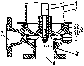
[0004] Aiming at the above-mentioned deficiencies in the prior art, the technical problem to be solved by the present invention is to provide a self-balancing vertical centrifugal pump with axial force, so as to avoid the problem that the downward axial load is too large when the vertical centrifugal pump is working, which affects the service life. When the vertical centrifugal pump is working, the impeller generates an upward axial force to offset the self-weight of the rotor system so that the axial load is self-balanced, the axial load is reduced, the failure rate is reduced, and the service life of the equipment is improved.

Method used


Image

  • Axial force self-balancing vertical centrifugal pump
  • Axial force self-balancing vertical centrifugal pump
  • Axial force self-balancing vertical centrifugal pump

Examples


Embodiment 1

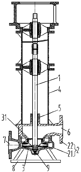
[0023] see figure 2 , an axial force self-balancing vertical centrifugal pump according to Embodiment 1 of the present invention, including a pump casing 2 and a vertical pump shaft 1, the upper end of the pump shaft 1 is connected to a motor (not shown in the figure), and the lower end extends into the pump casing 2 and connected with the impeller 3 in the pump casing 2 to drive the impeller 3 to rotate, the pump casing 2 includes a pump body 21 and a pump cover 22, the pump cover 22 is connected with a motor bracket 4 for placing the motor, The position where the pump shaft 1 passes through the pump cover 22 is provided with a connecting bearing 5 to increase the stability of the pump shaft 1 when it rotates. There are also two supports in the motor bracket 4 that are provided with connecting parts and are connected to the pump shaft 1 through bearings; The side of the cover 22 is provided with a water inlet 6, the water inlet 6 and the impeller 3 have a height difference i...

Embodiment 2

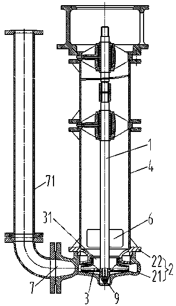
[0026] see image 3 The difference between Embodiment 2 and the axial force self-balancing vertical centrifugal pump in Embodiment 1 is that the axial force self-balancing vertical centrifugal pump in Embodiment 2 is a submerged pump. The whole pump casing 2 needs to be placed in the underwater operation, its water outlet 7 is connected to the upward water outlet pipe 71, its motor support 4 is a cylindrical structure, its pump cover 22 is a hollow ring structure, the inner cavity of the motor support 4 and the pump The hollow part of the cover 22 is connected, and the water inlet 6 is opened on the side wall of the motor bracket 4, and the water inlet 6 is also located on the impeller 3, so that the manufacture of the pump cover 22 is simpler; other similar effects will not be repeated; Sump pumps are also usually not provided with a base.

Embodiment 3

[0028] see Figure 4 , the third embodiment is a further optimized structure on the basis of the second embodiment, the lower end of the pump body 21 is still closed, the tail end of the pump shaft 1 continues to extend downwards and the extended shaft section is covered with a shaft sleeve 10, the shaft The upper end of the sleeve 10 abuts against the lower end of the impeller 3, and the lower end of the sleeve 10 is pressed upward by the impeller nut 9 threaded with the pump shaft 1; the outer side of the sleeve 10 is connected with the pump body 21 through the connecting bearing 5. In this way, although the middle part of the pump cover 22 is designed as a hollow structure for the passage of fluid, the pump cover 22 and the pump shaft 1 are not connected by bearings, but the shaft section of the pump shaft 1 below the impeller 3 is still connected to the pump by connecting the bearing 5. The pump body 21 of the shell 2 is kept connected, which can also ensure the rotation s...


PUM


Abstract

The invention relates to an axial force self-balancing vertical centrifugal pump. The axial force self-balancing vertical centrifugal pump comprises a pump shell and a vertical pump shaft. The upper end of the pump shaft is connected with a motor, the lower end of the pump shaft extends into the pump shell and is connected with an impeller in the pump shell to drive the impeller to rotate, and thepump shell is provided with a water outlet. The water inlet end of the impeller is upward. The axial force self-balancing vertical centrifugal pump further comprises a water inlet, a height difference exists between the water inlet and the impeller in the vertical direction, and the water inlet is located above the impeller. The shaft segment, below the impeller, of the pump shaft is connected with the pump shell through a bearing so that stability can be improved. According to the axial force self-balancing vertical centrifugal pump, the loss of flowing energy of the fluid in the pump is small, the pump shaft is retained to be connected with the bearing of the pump shell, and the pump shaft rotates more stably. The water inlet end of the impeller is upward, during working, the fluid is sucked in through the water inlet, the fluid flows to the position above the axis position of the impeller through a suction runner and is further sucked in through the impeller and then thrown out, due to the reactive force of the fluid, the impeller can transit upward axial force to the pump shaft, the dead load of a rotor system is offset and balanced, the axial load is small, correspondingly, the failure rate is reduced, and the service life is prolonged.

Description

technical field [0001] The invention belongs to the technical field of non-variable pumps in liquid variable capacity machines, and in particular relates to an axial force self-balancing vertical centrifugal pump. Background technique [0002] A centrifugal pump is a pump that delivers fluid by the centrifugal force generated when the impeller rotates. The fluid is sucked in from the water inlet and pumped out from the water outlet. When working, the pump shaft drives the impeller in the pump casing to rotate at a high speed, and the fluid in the pump casing is thrown to the outer edge of the impeller under the action of centrifugal force, and flows into the pressure water pipeline through the volute flow channel of the pump casing to be pumped out. , the negative pressure area is formed because the fluid is thrown out, the external fluid is sucked from the water inlet under the pressure, and flows continuously to the negative pressure area of ​​the impeller axis through the...

Claims


Application Information

Patent Timeline
Patent Type & Authority Applications(China)
IPC IPC(8): F04D1/00F04D13/06F04D29/66F04D29/42
CPCF04D1/00F04D13/06F04D29/4293F04D29/662
Inventor 罗绍华李方忠胡冬冬田夏夏赵建琳
Owner 重庆水泵厂有限责任公司
Learn More