Ship bottom silt removal robot

A robot and ship bottom technology, applied to ship cleaning devices, ship hulls, ship construction, etc., can solve problems such as heavy workload and long maintenance work time

Pending Publication Date: 2018-10-12
HEBEI UNIV OF TECH
View PDF8 Cites 0 Cited by
  • Summary
  • Abstract
  • Description
  • Claims
  • Application Information

AI Technical Summary

Problems solved by technology

Both of the above methods require manual participation, and the workload is heavy, and the maintenance work takes a long time

Method used


Image

  • Ship bottom silt removal robot
  • Ship bottom silt removal robot

Examples


Embodiment 1

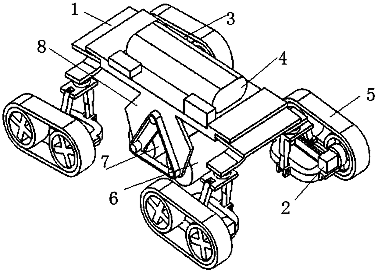
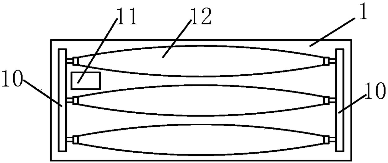
[0018] refer to figure 1 , the present invention proposes a ship bottom dredging robot for dredging the iron ship bottom, which includes a vehicle frame 1, four crawler walking mechanisms 3 placed on the vehicle frame 1, a buoyancy mechanism and a dredging mechanism. Both sides of the bottom of the vehicle frame 1 extend downward to form two wing plates 8 .

[0019] The four crawler running mechanisms 3 are respectively arranged at four corners of the vehicle frame 1 , and the crawler belt running mechanisms 3 include a first motor 2 and two magnetic wheels. The two magnetic wheels are connected through a crawler belt 5, and the magnetic wheels are at least partially made of magnetic materials. The first motor 2 is connected with the magnetic wheel for driving the magnetic wheel to rotate.

[0020] The dredging mechanism includes a first brush roller 6 and a second brush roller 7, and the axial direction of the first brush roller 6 and the second brush roller 7 is consistent...

Embodiment 2

[0031] The difference from Embodiment 1 is that in order to realize the intelligent control of the robot, the submarine transponder can be arranged in the planned working water area in advance. When the dredging robot is attached to the bottom surface of the ship, the interrogator embedded in the dredging robot sends out an inquiry signal and receives the signal from the transponder, and based on this, the distance between the dredging robot and each transponder is calculated. The absolute spatial position of the dredging robot can be calculated by using spherical intersection, so as to realize the positioning, and then the movement of the dredging robot can be planned independently or artificially controlled.

[0032] The whole vehicle frame 1 adopts 1060 aluminum alloy profile, which has low density and high strength, and is treated with anti-corrosion spray paint. The on-load motors are all selected underwater special models.

[0033] A control system processor is arranged...


PUM


Abstract

The invention relates to a ship bottom silt removal robot. The ship bottom silt removal robot is used for removing the tilt at the bottom of an iron ship. The ship bottom silt removal robot comprisesa vehicle frame, four crawler walking mechanisms mounted on the vehicle frame, a buoyancy mechanism and a silt removal mechanism, and both sides of the bottom of the vehicle frame extend downwards toform two wing panels. The four crawler walking mechanisms are separately arranged at four corners of the vehicle frame. Each of the crawler walking mechanisms comprises a first motor and two magneticwheels, and the two magnetic wheels are connected by crawlers in a transmission mode. The silt removal mechanism comprises a first brush roller and a second brush roller. The first brush roller and the second brush roller are driven to rotate by a driving mechanism.

Description

technical field [0001] The invention relates to the field of ship bottom dredging, in particular to a ship bottom dredging robot. Background technique [0002] There are two conventional ways of dredging the hull of a ship: in water, the divers use a special high-pressure water gun on the workbench that has been built in the early stage to wash; on land, the bottom of the ship is cleaned manually in a dry dock. The above two methods all require manual participation, and while the workload is heavy, the maintenance operation takes a long time. Contents of the invention [0003] The present invention aims at the deficiencies in the prior art and provides a ship bottom dredging robot. [0004] In order to solve the above problems, the technical scheme adopted in the present invention is as follows: [0005] A ship bottom dredging robot is used for dredging the iron ship bottom, comprising: a vehicle frame, four crawler walking mechanisms placed on the vehicle frame, a buoya...

Claims


Application Information

Patent Timeline
Patent Type & Authority Applications(China)
IPC IPC(8): B63B59/08
CPCB63B59/08
Inventor 韩旭胡俊宇
Owner HEBEI UNIV OF TECH
Why Eureka
Try Eureka