Automatic oil lubrication device of bearing of wheel or pulley

An oil lubricating and pulley technology, applied in the field of automatic oil lubricating devices for wheels and pulley bearings, can solve the problems of long downtime, difficult control of grease replenishment quality, grease extrusion, etc. The effect of downtime risk

Pending Publication Date: 2018-09-28
厦门迈凯科机电设备有限公司
View PDF6 Cites 5 Cited by
  • Summary
  • Abstract
  • Description
  • Claims
  • Application Information

AI Technical Summary

Problems solved by technology

[0003] 1. Time-consuming and labor-intensive
[0004] 2. The replenishment quality of lubricating grease is difficult to control, completely relying on manual on-site control
[0005] 3. The sensor system cannot be used to monitor the lubrication effect
[0006] 4. It needs to be shut down when replenishing grease, high maintenance cost and long downtime
[0007] 5. It is cumbersome to replenish the grease, and it is necessary to replenish and check the grease one by one, and the chance of work-related injuries is high
[0008] 6. When the grease is replenished, the old grease will be squeezed out, causing environmental pollution
[0009] 7. With the rise of labor costs, it becomes more and more uneconomical

Method used


Image

  • Automatic oil lubrication device of bearing of wheel or pulley
  • Automatic oil lubrication device of bearing of wheel or pulley
  • Automatic oil lubrication device of bearing of wheel or pulley

Examples


Embodiment Construction

[0035] Below in conjunction with accompanying drawing and embodiment the present invention is described in detail:

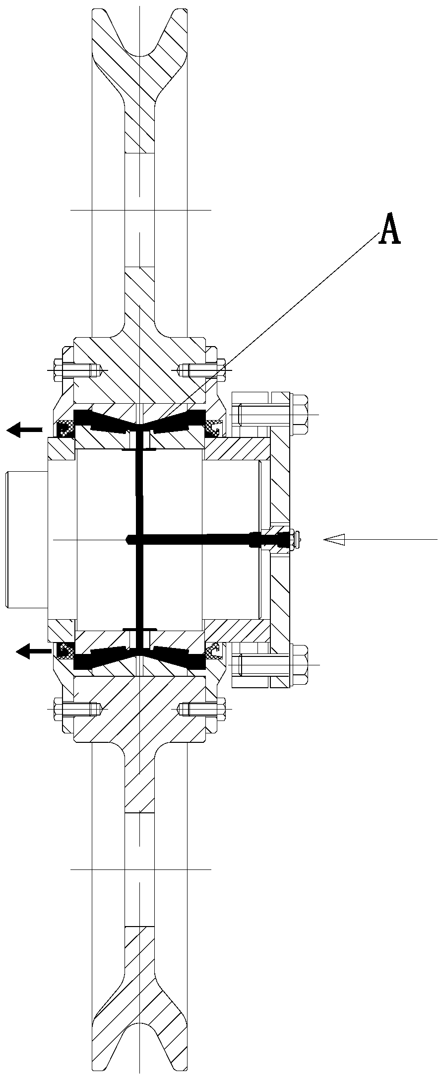
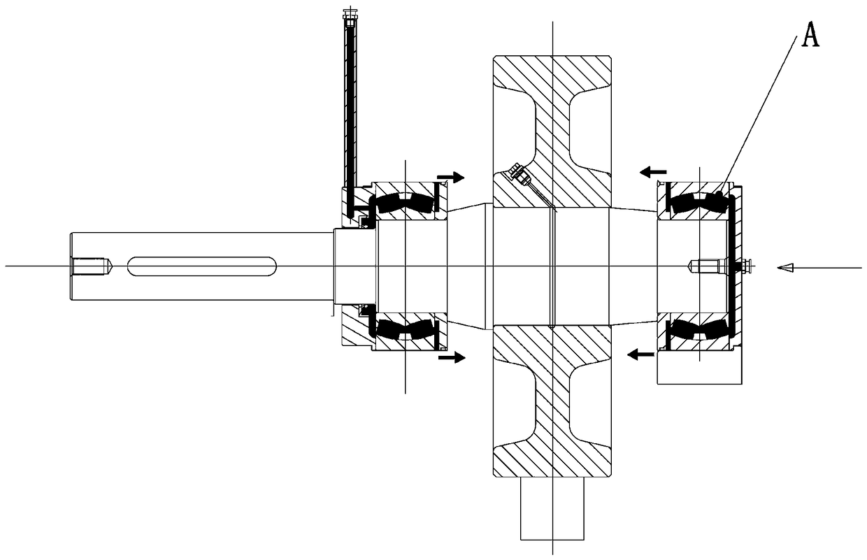
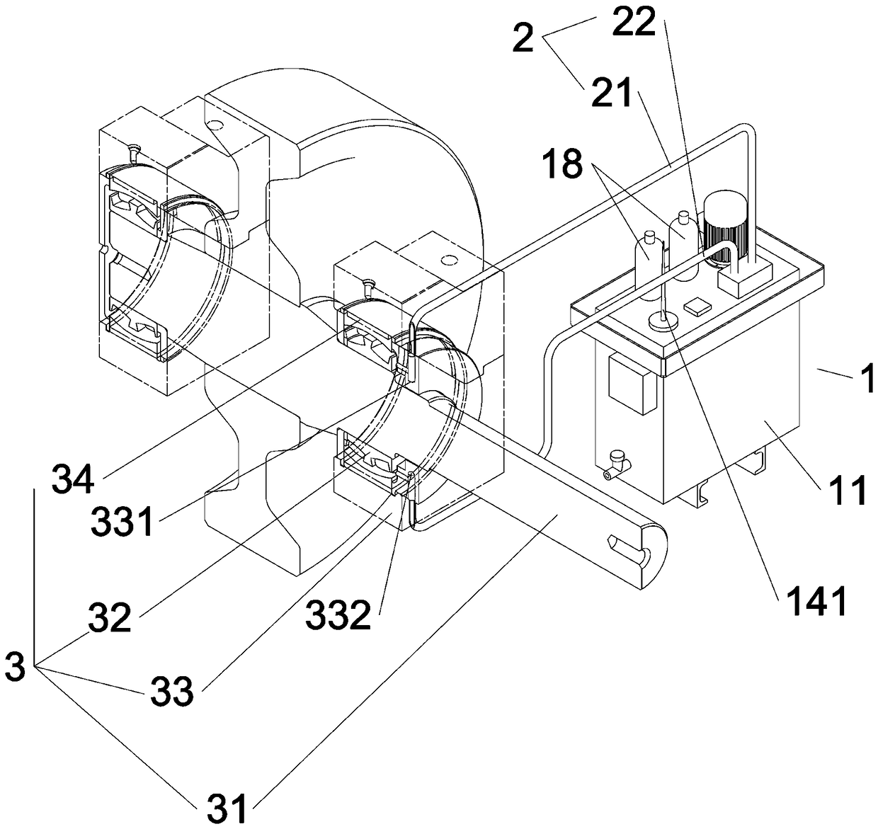
[0036] Figure 3-Figure 11 Shown is an embodiment of the present invention.

[0037] An automatic oil lubrication device for wheel or pulley bearings, comprising a lubrication system hydraulic station 1 and an oil lubrication mechanism 2, the lubrication system hydraulic station 1 is equipped with an oil tank 11, a motor 12, a valve block 13, an oil level and cleanliness detector 14, Output pipe 15, recovery pipe 16; oil lubrication mechanism 2 includes oil inlet pipe 21 and oil return pipe 22 respectively connected to the oil supply place of wheel 3 or pulley 4; wherein, the valve block 13 in the hydraulic station 1 of the lubrication system is connected to the oil tank 11 respectively. The output pipe 15, the recovery pipe 16, and the oil inlet pipe 21 and the oil return pipe 22 in the oil lubrication mechanism 2, the hydraulic oil in the oil tank 11 is sent ...


PUM


Abstract

The invention discloses an automatic oil lubrication device of a bearing of a wheel or a pulley. The automatic oil lubrication device comprises a lubrication system hydraulic station and an oil lubrication mechanism, wherein the lubrication system hydraulic station is internally provided with an oil tank, a motor, a valve block, an oil level and cleanliness detector, an output pipe and a recoverypipe; the oil lubrication mechanism comprises an oil inlet pipe and an oil return pipe, and the oil inlet pipe and the oil return pipe both are connected to an oil supply position of the wheel or thepulley; and the valve block of the lubrication system hydraulic station is connected to the output pipe and the recovery pipe in the oil tank and is connected to the oil inlet pipe and the oil returnpipe of the oil lubrication mechanism, hydraulic oil in the oil tank is sent to the output pipe through the motor, the output pipe is connected with the valve block, and the valve block is connected with the oil inlet pipe to convey the hydraulic oil to the oil supply position of the wheel or the pulley; the used residual oil flows back to the valve block through the oil return pipe connected withthe valve block, and then flows back to the oil tank through the recovery pipe connected with the valve block; and the oil level and cleanliness detector is arranged in the oil tank, and the detection information is transmitted to a control center through a transmission device. The automatic oil lubrication device has the advantages that automatic control is realized, and manual intervention is not needed; and real-time detection is realized, and the lubricating quality is ensured.

Description

Technical field: [0001] The invention relates to a bearing lubricating system for wheels, pulleys or pulley blocks, in particular to an automatic oil lubricating device for wheel and pulley bearings. Background technique: [0002] In the prior art, the bearing lubrication of wheels and pulleys (groups) all adopts grease lubrication, and regular manual or semi-automatic replenishment of grease ensures the lubrication of bearing A, such as figure 1 and figure 2 As shown, its main disadvantages are: [0003] 1. Time-consuming and labor-intensive. [0004] 2. The replenishment quality of lubricating grease is difficult to control, and it is completely controlled by manual on-site control. [0005] 3. The sensor system cannot be used to monitor the lubrication effect. [0006] 4. It needs to be shut down when replenishing grease, the maintenance cost is high, and the downtime is long. [0007] 5. It is cumbersome to replenish the grease, and it is necessary to replenish and...

Claims


Application Information

Patent Timeline
Patent Type & Authority Applications(China)
IPC IPC(8): F16C33/66F16N7/40F16N29/04F16N39/06
CPCF16C33/6659F16C33/667F16C33/6674F16C2326/02
Inventor 王文红于民权黄朝毅
Owner 厦门迈凯科机电设备有限公司
Why Eureka
Try Eureka