A composite braking system

A compound brake and transmission shaft technology, applied in the direction of brake actuators, gear transmission mechanisms, mechanical equipment, etc., can solve the problems of increased manufacturing costs, deviation from the driving route, and a large number of clutches, etc., to achieve reasonable structural design and reduce manufacturing costs. The effect of high cost and safety factor

Active Publication Date: 2020-04-28
SHANTUI CONSTR MASCH CO LTD
View PDF6 Cites 0 Cited by
  • Summary
  • Abstract
  • Description
  • Claims
  • Application Information

AI Technical Summary

Problems solved by technology

For some workplaces with explosion-proof requirements such as underground mines, the above-mentioned braking methods are strictly prohibited, mainly to prevent the explosion of flammable gases; There is a differential function in the middle, so the drive axle must be equipped with left and right brakes. Generally, vehicles have front and rear drive axles, so four sets of brakes are required, that is, four sets of wet brake clutches need to be added to the drive axle. Due to the high pressure of the hydraulic system of the drive axle, The heat dissipation effect is poor, so the performance requirements for the clutch that need to be increased are very high, resulting in a substantial increase in additional manufacturing costs, and pushing up the manufacturing cost of vehicles with explosion-proof requirements. Therefore, this type of clutch is only used in some high-end models at present.
Moreover, the technical solution of adding four sets of clutches to the drive axle belongs to the end braking of the transmission system. The consistency of the braking needs to be synchronized, and the requirements for the control consistency of the four sets of clutches are high. The more the number of clutches, the more difficult it is to grasp the consistency
If there is a large braking force on one side during use, the vehicle will easily deviate during the braking process, resulting in deviation from the driving route and potential safety hazards; moreover, the drive axle itself does not have a special heat dissipation system, causing the clutch The heat dissipation effect is poor. In order to ensure the braking effect during use, the quality of the clutch is required to be high, which increases the manufacturing cost.
At the same time, the number of clutches used in this structure is large, which increases the structural complexity and manufacturing cost of the driving axle, and further increases the manufacturing cost of the driving axle.
The disc brake or drum brake used in the parking brake of the transmission can meet the use requirements simply considering the parking brake, but in the working conditions with explosion-proof requirements, in order to prevent the sparks generated by emergency braking from causing explosions, bring greater danger, so the above-mentioned braking method is strictly forbidden to be used as emergency braking in the working conditions with explosion-proof requirements; in order to improve the braking effect of the driving vehicle in the working conditions with explosion-proof requirements and ensure To improve the safety of driving, it is necessary to design a new braking system

Method used


Image

  • A composite braking system
  • A composite braking system

Examples


Embodiment Construction

[0017] In order to clearly illustrate the technical features of this solution, the present invention will be described in detail below through specific implementation modes and in conjunction with the accompanying drawings.

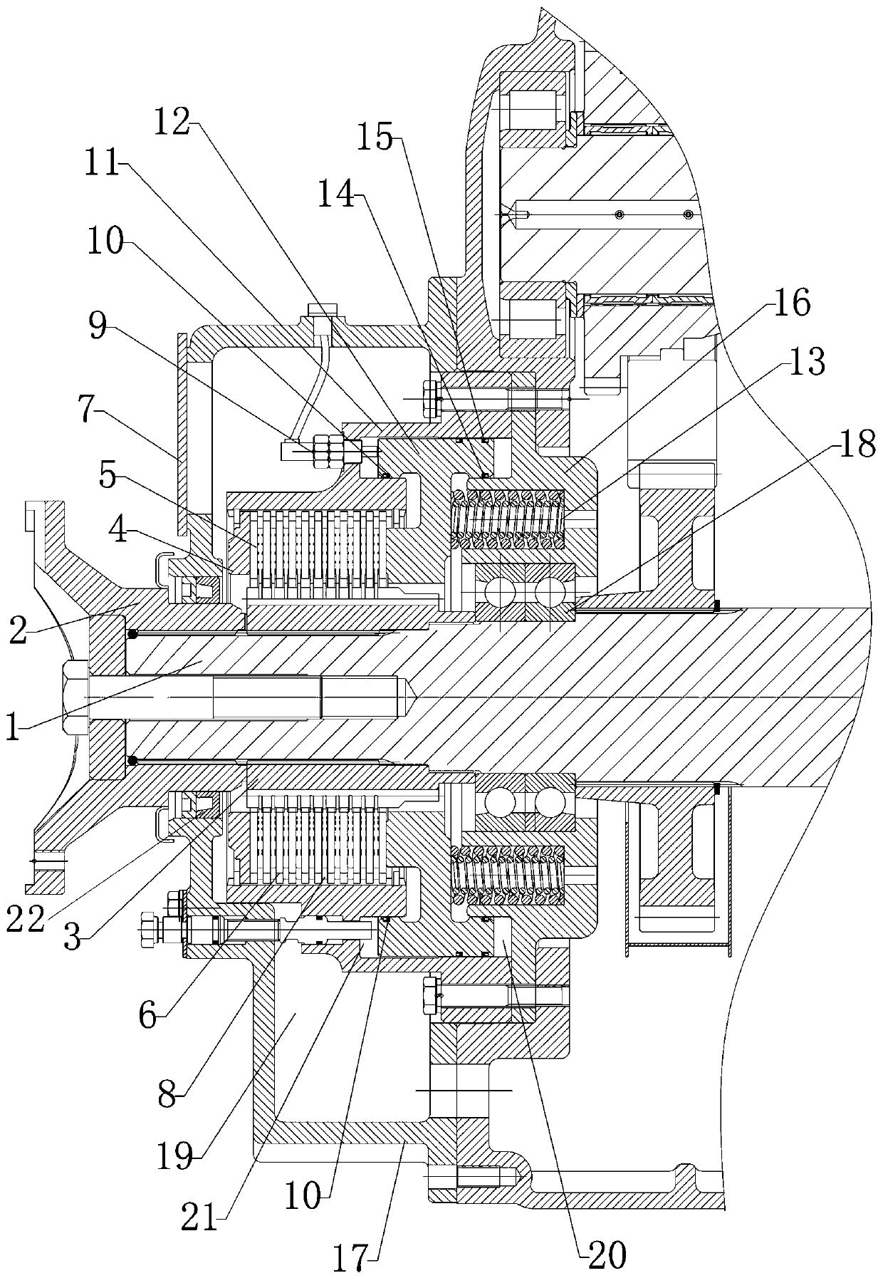
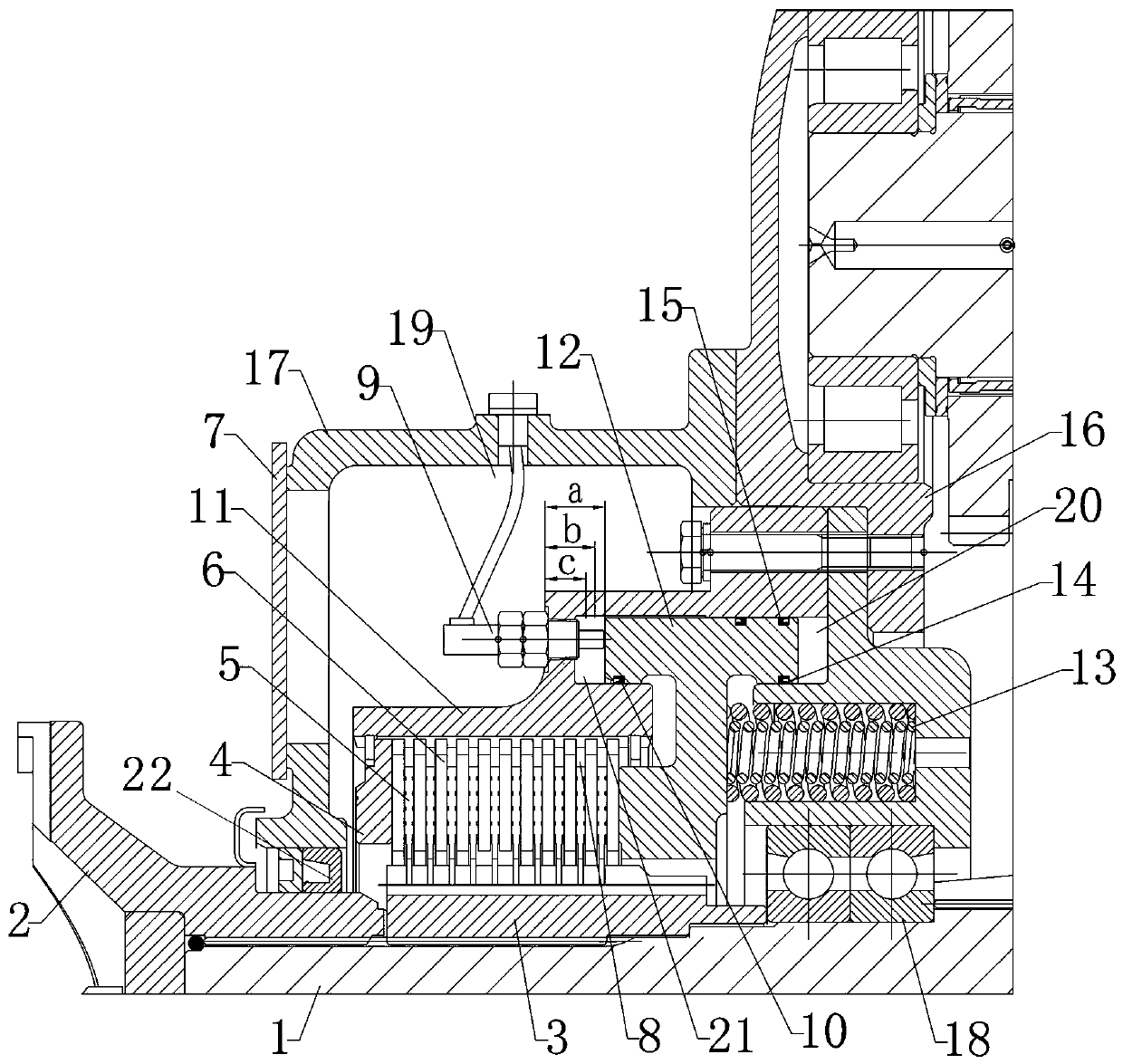
[0018] like Figure 1-2 As shown in , a composite braking system includes a base 16, which is fixedly connected to the main body of the gearbox, and the end of a transmission shaft 1 moves through the communication cavity in the middle of the base 16 and passes through The bearing 18 is matched, and the end of the transmission shaft 1 extends out of the casing 17 of the gearbox main body and is fixedly connected with an output flange 2, and the outer end of the transmission shaft 1 and the output flange 2 is connected by a connecting bolt Tightly connected, the inner end of the output flange 2 is sleeved on the outer wall of the transmission shaft 1, and an end bearing 22 is arranged in the through hole outside the casing 17 of the main body of the gearbo...


PUM


Abstract

The invention relates to the field of engineering machinery, in particular to a composite braking system. The composite braking system comprises a seat, wherein the seat is fixedly connected with a gearbox main body; an end of a transmission shaft extends out of a shell of the gearbox main body and is fixedly connected with an output flange; the transmission shaft is connected with the outer end of the output flange in a fastened manner through a connecting bolt; the inner end of the output flange is in sleeve connection to the outer side wall of the transmission shaft; a main cavity is formedbetween the shell of the gearbox main body and the transmission shaft; the transmission shaft in the main cavity is fixedly connected with a bidirectional piston; an oil cylinder body of which the rear section inner side wall is matched with the outer side wall of the bidirectional piston is arranged in the main cavity and positioned on the outer side of the bidirectional piston; the inner end ofthe oil cylinder body is fixedly connected with the gearbox main body; and a buffering auxiliary device is arranged between the seat and the bidirectional piston. The composite braking system is reasonable in structural design; on the basis of reduction of the manufacturing cost, vehicle emergency braking, parking braking, running braking and micro-motion functions are fulfilled; and when the composite braking system is used, the safety factor is high.

Description

technical field [0001] The invention relates to the field of engineering machinery, in particular to a composite braking system. Background technique [0002] Existing loader gearboxes mostly use drum or caliper disc brakes for parking brakes, and dry brakes on the drive axle for service brakes. For some workplaces with explosion-proof requirements such as underground mines, the above-mentioned braking methods are strictly prohibited, mainly to prevent the explosion of flammable gases; There is a differential function in the middle, so the drive axle must be equipped with left and right brakes. Generally, vehicles have front and rear drive axles, so four sets of brakes are required, that is, four sets of wet brake clutches need to be added to the drive axle. Due to the high pressure of the hydraulic system of the drive axle, The heat dissipation effect is poor, so the performance requirements for the clutch that need to be increased are very high, resulting in a substantial...

Claims


Application Information

Patent Timeline
Patent Type & Authority Patents(China)
IPC IPC(8): F16D65/14F16D121/02
CPCF16D65/14F16D2121/02
Inventor 李国强肖娜郭勇黄文生杜博群雷福斗赵如愿孙守猛
Owner SHANTUI CONSTR MASCH CO LTD
Why Eureka
Try Eureka