Method for designing multi-section mixed valve element of regulating valve

A technology of mixed adjustment and design method, which is applied in the direction of valve lift, valve device, mechanical equipment, etc., which can solve the problems of improving the utilization rate of exhaust gas energy of the downstream turbine of the two-stage supercharging system, reducing the energy utilization rate of the downstream turbine, and poor adjustment characteristics. Good and other problems, to achieve the effect of improving the energy utilization rate of exhaust gas, less vortex, and high adjustment accuracy

Active Publication Date: 2018-09-28
CHINA NORTH ENGINE INST TIANJIN
View PDF5 Cites 6 Cited by
  • Summary
  • Abstract
  • Description
  • Claims
  • Application Information

AI Technical Summary

Problems solved by technology

After the gas flows through the flat valve core, due to the sudden change of the flow area, there are low-speed areas and vortices around the valve core, which reduces the energy utilization rate of the downstream turbine
Especially at small openings, the adjustment characteristics are not good
[0005] For the regulating valve of the two-stage booster system, it is hoped that it has a regulating characteristic close to the equal percentage flow characteristic: when the opening is small, the flow is small, the change of the flow is also small, and the adjustment is smooth and gentle; when the opening is large, the flow is large, The change of the flow rate is also large, and the adjustment is sensitive and effective, which is beneficial to the precise energy distribution of the high and low pressure stage turbines of the two-stage supercharger system, but the regulating valve with the flat valve core structure cannot meet this requirement, and the adjustment accuracy is poor; There are low-speed areas and swirls, which are not conducive to improving the utilization rate of exhaust gas energy of the downstream turbine of the two-stage supercharging system

Method used


Image

  • Method for designing multi-section mixed valve element of regulating valve
  • Method for designing multi-section mixed valve element of regulating valve
  • Method for designing multi-section mixed valve element of regulating valve

Examples


Embodiment Construction

[0025] It should be noted that, in the case of no conflict, the embodiments of the present invention and the features in the embodiments can be combined with each other.

[0026] The present invention will be described in detail below with reference to the accompanying drawings and examples.

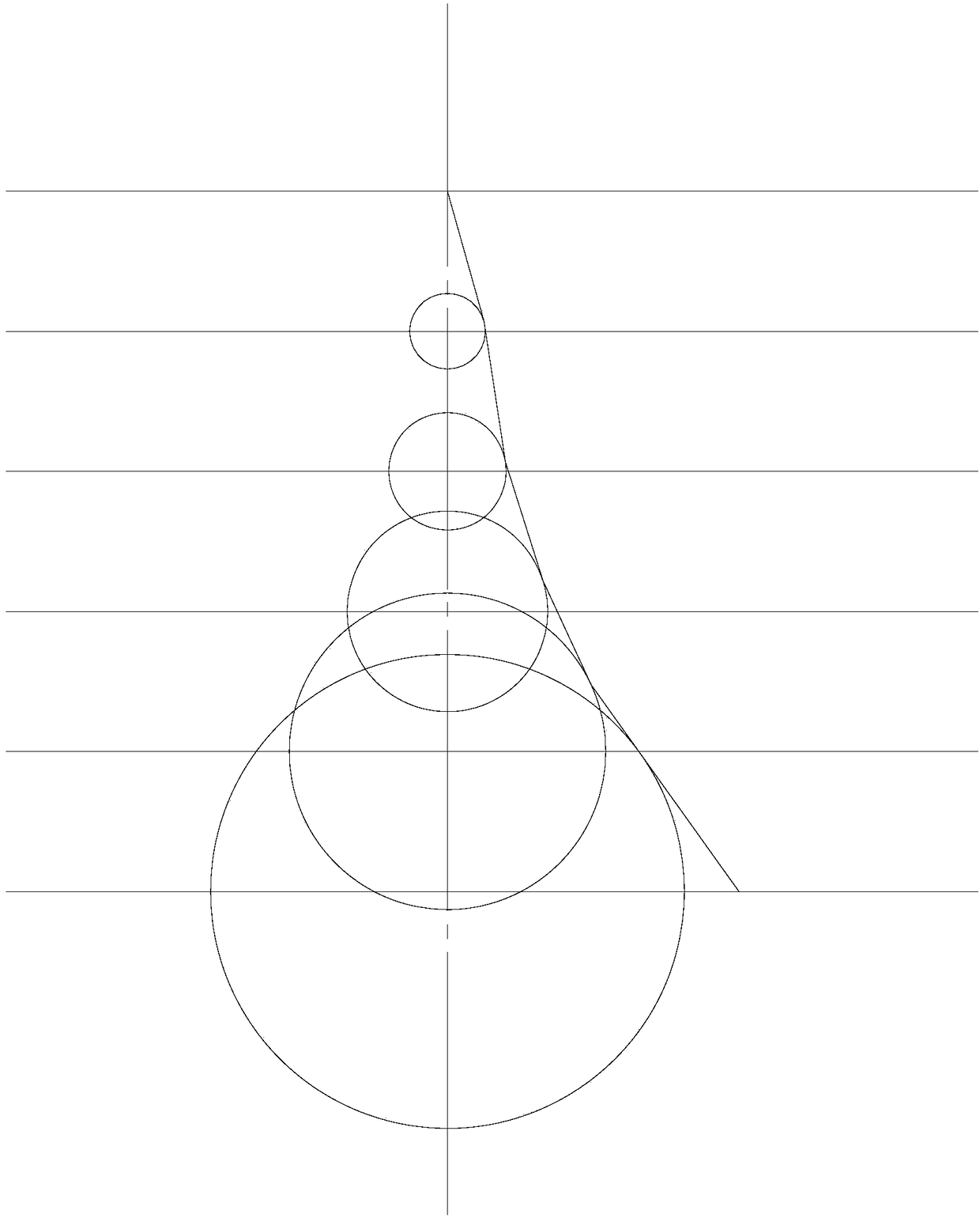
[0027] The method for designing the spool of the multi-section mixing control valve according to the embodiment of the present invention includes the following steps:

[0028] 1) The flow formula of the ideal equal percentage flow characteristic is as follows:

[0029]

[0030] In the formula, Q is the actual flow through the valve, Qmax is the maximum flow of the valve, l is the actual stroke of the valve, L is the maximum stroke of the valve, R is the adjustable ratio, and the adjustable ratio R is defined as the maximum flow that the valve can control Ratio to the minimum controllable flow.

[0031] In this embodiment, the valve diameter is 25mm as an example, and the adjustable ...


PUM


Abstract

The invention provides a method for designing a multi-section mixed valve element of a regulating valve. The method comprises the steps: (1) obtaining the flow of the valve element under different opening and the flow area under the corresponding opening by calculation; (2) calculating the flow area needed by equal percentage flow characteristics under different opening; (3) obtaining circle diameters corresponding to all sections; (4) completing the outer contour of the multi-section mixed valve element; (5) determining the opening needing to be optimized; and (6) obtaining the improved valveelement structure. The method has the following advantages that the degree of change of the flow area formed between the profile of the multi-section mixed valve element and a valve hole has higher regulation precision relative to the gentle change of a flat valve element, and the regulating characteristic is close to the regulating characteristic of the equal percentage flow characteristics; theregulating valve with the multi-section mixed valve element is opened at different angles, gas flows through the profile of the multi-section mixed valve element, airflow is smooth, the formed vortexis less, and the energy utilization of exhaust gas of the downstream turbines of a two-stage supercharging system is advantageously improved.

Description

technical field [0001] The invention belongs to the field of electromechanical technology, and in particular relates to a design method for a valve core of a multi-section mixing control valve. Background technique [0002] With the improvement of the power density of the internal combustion engine, the expansion of the speed range, and the diversification of applications, the pursuit of performance matching in all working conditions for the purpose of fuel economy and dynamic response has put forward new requirements for the supercharging system. The characteristic and time task profile, and the adjustable supercharging system that realizes the supercharging parameter change through the switching of the regulating valve have become research hotspots. The adjustable supercharging system represented by the two-stage supercharging can not only meet the design working conditions of the engine, but also adapt to the working conditions of variable working conditions and different...

Claims


Application Information

Patent Timeline
Patent Type & Authority Applications(China)
IPC IPC(8): F16K1/36F02B37/22
CPCF02B37/22F16K1/36Y02T10/12
Inventor 王振彪石磊邓康耀刘畅
Owner CHINA NORTH ENGINE INST TIANJIN
Why Eureka
Try Eureka