Groove sintering type porous layer composite liquid absorbing core heat column

A porous layer and liquid-absorbing core technology, applied in indirect heat exchangers, lighting and heating equipment, etc., can solve the problems of complex internal structure of heat pipes, unfavorable repair and inspection of internal components of the pipe body, and achieve convenient reassembly and improvement Unblocking effect, effect of improving reflux efficiency

Inactive Publication Date: 2018-09-28
GUANGDONG TECHN COLLEGE OF WATER RESOURCES & ELECTRIC ENG
View PDF8 Cites 2 Cited by
  • Summary
  • Abstract
  • Description
  • Claims
  • Application Information

AI Technical Summary

Problems solved by technology

The latest research shows that the internal structure of heat pipes will become more and more complex
For example, the spiral power heat pipe disclosed in patent application 201611099102.9 is used for large-scale device systems. Many components are integrated in the disclosed technical solution. If the traditional method of welding and sealing the tube body is adopted, it will be extremely unfavorable for the subsequent repair of the internal components of the tube body. detection

Method used


Image

  • Groove sintering type porous layer composite liquid absorbing core heat column
  • Groove sintering type porous layer composite liquid absorbing core heat column
  • Groove sintering type porous layer composite liquid absorbing core heat column

Examples


Embodiment Construction

[0028] In order to make the objectives, technical solutions, and advantages of the embodiments of the present invention clearer, the technical solutions in the embodiments of the present invention will be described clearly and completely in conjunction with the accompanying drawings in the embodiments of the present invention. Obviously, the described embodiments It is a part of the embodiments of the present invention, not all the embodiments. Based on the embodiments of the present invention, all other embodiments obtained by those of ordinary skill in the art without creative work shall fall within the protection scope of the present invention.

[0029] It should be noted that when an element is referred to as being "fixed to" another element, it can be directly on the other element or a central element may also exist. When an element is considered to be "connected" to another element, it can be directly connected to the other element or an intermediate element may be present ...


PUM

PropertyMeasurementUnit
particle diameteraaaaaaaaaa
pore sizeaaaaaaaaaa

Abstract

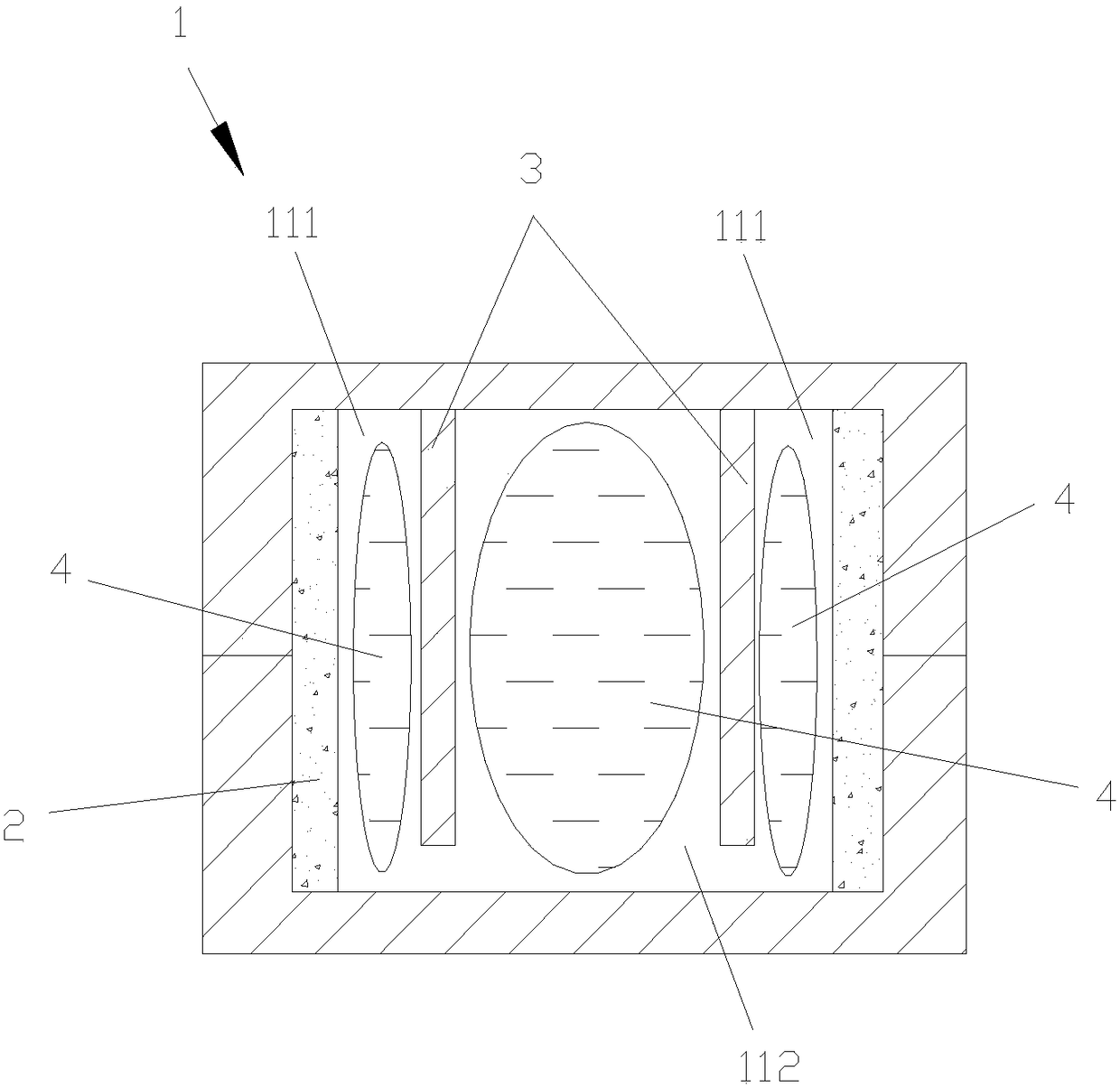
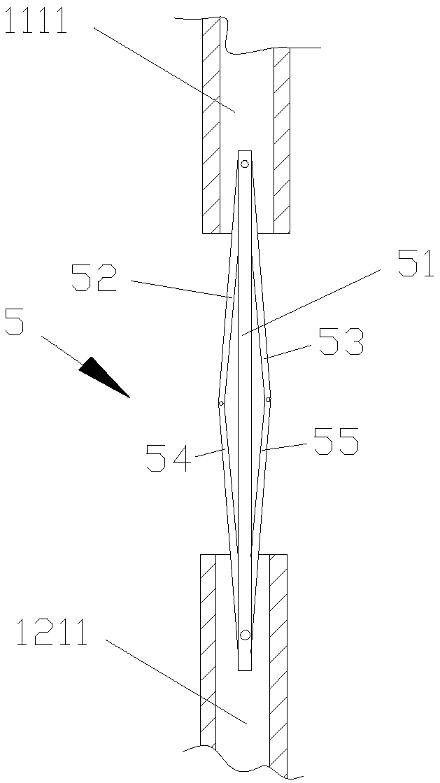
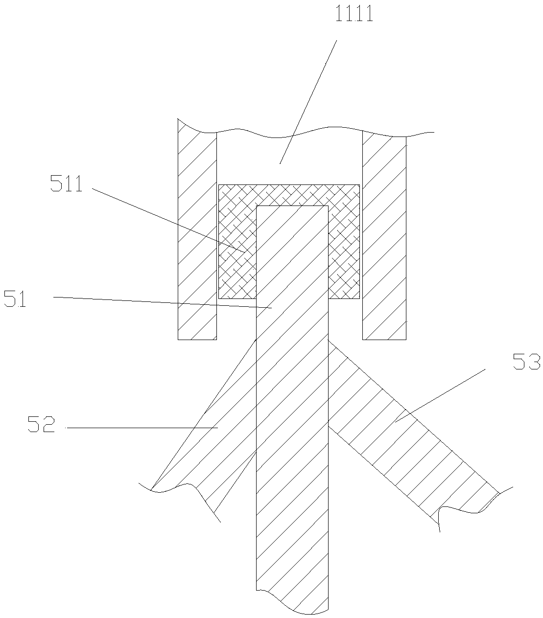
The invention discloses groove sintering type porous layer composite liquid absorbing core heat column. The groove sintering type porous layer composite liquid absorbing core heat column comprises a pipe body and a multi-groove flowing channel, wherein grooves in the multi-groove flowing channel extend from one end of the pipe body to the other end of the pipe body; two elastic separating plates are arranged in an inner empty cavity of the pipe body and divide the inner empty cavity of the pipe body into two side chambers and an intermediate chamber in the width direction; the intermediate chamber is positioned between the two side chambers; a flexible metal inner tank is stored in each of the side chambers and the intermediate chamber; the pipe body comprises a first pipe body and a second pipe body which are oppositely closed to each other; an elastic supporting part which can be contracted into the pipe body is connected between the first pipe body and the second pipe body; and thefirst pipe body and the second pipe body can be stretched to form an opening through the elastic supporting part. The groove sintering type porous layer composite liquid absorbing core heat column hasthe advantages that the capillary pressure is high; the reflowing resistance is small; the opening is conveniently formed, so that elements in the pipe body can be conveniently detected, repaired andreplaced.

Description

Technical field [0001] The invention relates to the technical field of electronic devices, in particular to a grooved sintered porous layer composite wick thermal column. Background technique [0002] The heat column, also known as the heat pipe, makes full use of the principle of heat conduction and the rapid heat transfer properties of the phase change medium. The heat of the heating object is quickly transferred to the heat source through the heat pipe, and its thermal conductivity exceeds the thermal conductivity of known metals. [0003] The existing heat pipe generally includes a hollow and airtight metal shell, a capillary structure arranged in the shell, and a working medium filled in the shell. The capillary structure is usually a grooved structure, a sintered powder structure or a wire mesh structure. . Among them, the wire mesh structure has been gradually replaced by other forms of wicks due to poor process repeatability and inability to adapt to pipe bending. [0004] ...

Claims


Application Information

Patent Timeline
Patent Type & Authority Applications(China)
IPC IPC(8): F28D15/02F28D15/04
CPCF28D15/0233F28D15/0241F28D15/0275F28D15/0283F28D15/046
Inventor 陶素连
Owner GUANGDONG TECHN COLLEGE OF WATER RESOURCES & ELECTRIC ENG
Why Eureka
Try Eureka