
Rotating shaft calibration method and system for 3D rotary scanning system

A technology of rotating scanning and calibration method, applied in the field of 3D scanning, which can solve the problems of large amount of data and time-consuming processing.

Active Publication Date: 2018-09-28
SHANGHAI JIAO TONG UNIV
View PDF6 Cites 9 Cited by
  • Summary
  • Abstract
  • Description
  • Claims
  • Application Information

AI Technical Summary

Problems solved by technology

The amount of collected data is large and time-consuming to process

Method used


Image

  • Rotating shaft calibration method and system for 3D rotary scanning system
  • Rotating shaft calibration method and system for 3D rotary scanning system
  • Rotating shaft calibration method and system for 3D rotary scanning system

Examples


Embodiment approach

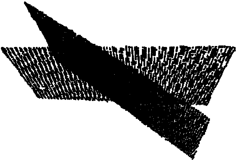
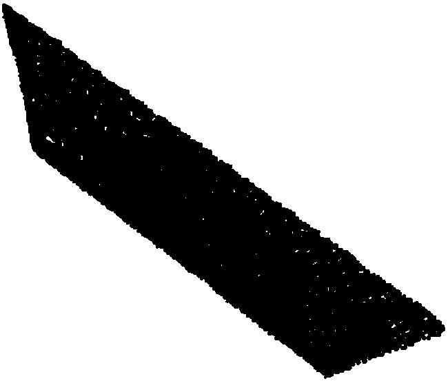
[0254]In actual operation, first place a rectangular flat plate on the turntable, scan to obtain the first point cloud data, and then scan again to obtain the second point cloud data after the turntable rotates at any known angle θ. The shape precision of the rectangle is not high, and the placement position is random, and it only needs to be fastened, which is why the method provided by the present invention is more convenient than other methods. In this preferred example, the first point cloud data and the second point cloud data collect four feature corner data p i ,q i ,Such as figure 1 , figure 2 As shown, the point cloud homogeneous transformation matrix of splicing the second point cloud data to the first point cloud data is obtained by using the control points. Due to the measurement error, it is impossible for the four feature points to correspond completely. Therefore, the least squares method is used to define the cost function T.

[0255] According to the rota...


PUM


Abstract

The invention provides a rotating shaft calibration method and system for a 3D rotary scanning system. The method comprises steps that a matching relationship solving step, the matching relationship of first point cloud data and second point cloud data is solved, the first point cloud data is acquired through scanning a to-be-measured object on a turning table without rotation, the second point cloud data is acquired through scanning the to-be-measured object on the turning table after known-angle rotation; and a splicing relationship solving step, reverse calibration of the axis of the turning table is carried out according to the matching relationship, and the splicing homogeneous transformation matrix is further solved. Correspondingly, the invention further provides a rotating shaft calibration system for the 3D rotary scanning system. The method is advantaged in that the reverse method is provided, device requirements are simple, the method has no shape and dimension accuracy requirements, the acquired data volume is greatly reduced, only two sets of data are required, the rapid calibration requirement can be satisfied, and accuracy is relatively high.

Description

technical field [0001] The present invention relates to the technical field of 3D scanning, in particular to a method and system for calibrating a rotating shaft of a 3D rotating scanning system. Background technique [0002] 3D rotary scanning refers to the use of 3D scanning technology to scan the 3D data of different angles of objects on the rotating platform. After obtaining a series of 3D data, calculate the matching relationship of the 3D data at each angle according to the calibrated axis of the turntable. The technique of stitching them together to form a complete three-dimensional data of an object. In the 3D rotating scanning platform, the splicing of two 3D data from different angles is calculated according to the calibrated rotation axis. Rotary axis calibration refers to the measurement of the spatial relationship between the turntable coordinate system and the three-dimensional data generation coordinate system of the object. According to the homogeneous trans...

Claims


Application Information

Patent Timeline
IPC IPC(8): G01B11/00G06K9/62
CPCG01B11/00G06F18/22
Inventor 刘成良朱凯贡亮李彦明黄亦翔刘翔鹏
Owner SHANGHAI JIAO TONG UNIV
Learn More