Fire-resistant and bend-resistant shielding flexible optical cable

A shielding and bending-resistant technology, applied in light guides, optics, optical components, etc., can solve problems affecting the service life of optical cables, poor fire performance, cracking and damage, etc., to improve heat dissipation and cold resistance, not easy to crack and damage, increase The effect of contact area

Active Publication Date: 2018-09-28
SHENZHEN SDG INFORMATION CO LTD
View PDF11 Cites 1 Cited by
  • Summary
  • Abstract
  • Description
  • Claims
  • Application Information

AI Technical Summary

Problems solved by technology

The flexible optical cable has greatly improved the heat dissipation function, but the structure is relatively simple, and it is prone to cracking and damage after repeated crimping or high pressure, and the fire performance is poor when subjected to high-temperature fires, which affects the service life of the optical cable.

Method used


Image

  • Fire-resistant and bend-resistant shielding flexible optical cable

Examples


Embodiment Construction

[0022] The technical solutions in the embodiments of the present invention will be clearly and completely described below in conjunction with the embodiments of the present invention. Apparently, the described embodiments are only some of the embodiments of the present invention, not all of them. Based on the embodiments of the present invention, all other embodiments obtained by persons of ordinary skill in the art without creative efforts fall within the protection scope of the present invention.

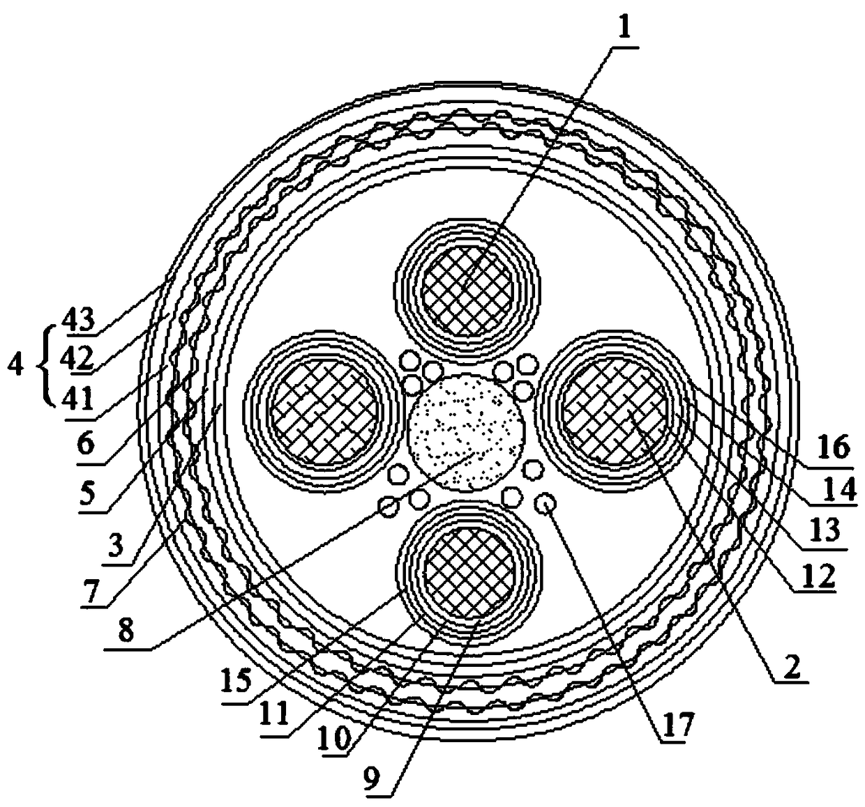
[0023] see figure 1 As shown, this embodiment provides a fireproof and bending resistant shielded flexible optical cable, which includes two optical cable cores 1 and two carbon fiber composite mandrels 2 arranged inside, an outer shielding layer 3 and an outer insulating layer arranged outside 4. A central reinforcing steel wire 8 is provided inside the optical cable core 1 and the carbon fiber composite mandrel 2 . Between the outer shielding layer 3 and the outer insulating la...


PUM


Abstract

The invention discloses a fire-resistant and bend-resistant shielding flexible optical cable which comprises two optical cable cores, two carbon fiber composite core rods, an outer shielding layer andan outer insulation layer, wherein the two optical cable cores and the two carbon fiber composite core rods are arranged in the optical cable, and the outer shielding layer and the outer insulation layer are arranged outside the optical cable. Center reinforced steel wires are arranged in the optical cable cores and the carbon fiber composite core rods, a water blocking layer, an inner cooling pipe and an outer cooling pipe are arranged between the outer shielding layer and the outer insulation layer, the outer insulation layer comprises a polytetrafluoroethylene layer, a ceramic silicon rubber layer, a high-flame-retardant halogen-free polyethylene layer which are sequentially arranged from inside to outside, the inner cooling pipe and the outer cooling pipe are made of high-molecular flexible materials, composite non-woven fabric layers, inner insulating layers and first fiber woven reinforcement layers are sequentially arranged on the outer layers of the optical cable cores, and fiber sheathes, high-temperature-resistant slip bands and second fiber woven reinforcement layers are sequentially arranged on the outer layers of the carbon fiber composite core rods. The optical cabledoes not easily crack or damage and is resistant to fire and high temperature after bearing multiple crimping and high pressure on the premise of ensuring the cooling performance and the shielding performance of the flexible optical cable.

Description

technical field [0001] The invention relates to the technical field of flexible optical cables, in particular to a fireproof and bending-resistant shielded flexible optical cable. Background technique [0002] An optical fiber is a light transmission tool that causes light to be transmitted by the principle of total reflection in a fiber made of glass or plastic. A cable containing an optical fiber is called an optical cable. During the laying and use of optical cables, certain requirements and standards need to be met. Usually, the cables are required to have properties such as tensile resistance, compression resistance, corrosion resistance, aging resistance, oil resistance, and fire resistance. With the advancement of science and technology and the development of society, higher requirements are put forward for optical cables. In many fields, optical cables are required to have better flexibility and folding characteristics, and to expand the application range of cables. ...

Claims


Application Information

Patent Timeline
Patent Type & Authority Applications(China)
IPC IPC(8): G02B6/44
CPCG02B6/4429G02B6/4436G02B6/44384
Inventor 王卉吕凌虹朱有胜
Owner SHENZHEN SDG INFORMATION CO LTD
Why Eureka
Try Eureka