PET (Positron Emission Tomography)-MRI (Magnetic Resonance Imaging) maximum posterior joint reconstruction method
What is AI technical title?
AI technical title is built by PatSnap AI team. It summarizes the technical point description of the patent document.
A PET-MRI and maximum a posteriori technology, applied in image data processing, complex mathematical operations, instruments, etc., can solve problems affecting image quality, increasing image artifacts, etc.
Active Publication Date: 2018-09-28
SOUTHERN MEDICAL UNIVERSITY
View PDF5 Cites 3 Cited by
Summary
Abstract
Description
Claims
Application Information
AI Technical Summary
This helps you quickly interpret patents by identifying the three key elements:
Problems solved by technology
Method used
Benefits of technology
Problems solved by technology
However, the features of PET and MRI images obtained by level set prior reconstruction appear to be interlaced, which increases image artifacts and seriously affects image quality.
Method used
Image
Click on the blue label to locate the original text in one second.
Reading with bidirectional positioning of images and text.
Examples
Embodiment 1
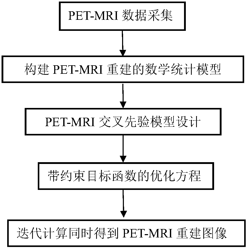
[0056] A PET-MRI maximum a posteriori joint reconstruction method, such as figure 1 , 2 , 4 and 5, including the following steps in turn:
[0057] Step 1, collecting PET data and MRI data of the subject;
[0058] Step 2, constructing a mathematical statistical model of PET-MRI joint reconstruction through the PET data and MRI data collected in step 1;
[0059] Step 3, in the mathematical statistical model of step 2, use the correlation between the PET image to be reconstructed and the MRI image to be reconstructed to design a cross prior model;
[0060] Step 4, combined with the cross-a priori model of step 3, the maximum a posteriori method is used to jointly reconstruct the mathematical statistical model of step 2, and an optimization equation with a constrained objective function is obtained;
[0061] In step five, iteratively calculate the optimization equation with the constrained objective function obtained in step four, and simultaneously obtain PET reconstructed ima...
Embodiment 2
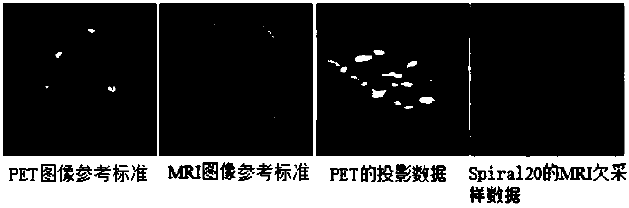
[0100] A PET-MRI maximum a posteriori joint reconstruction method, other features are the same as in Embodiment 1, the difference is that the acquisition object of this implementation is the brain, PET and MRI reconstructed images such as image 3 and 6 shown.
[0101] In order to verify the effect of the inventive method, Image 6 Shown are brain PET and MRI reconstructed images obtained by joint reconstruction of PET and Spiral20 undersampled MRI data by different methods, with the joint total variation (JTV) and linear level set (LPLS) prior proposed by M.J.Ehrhardt et al. Compared with the images reconstructed by the maximum a posteriori reconstruction method, the PET and MRI images reconstructed by the method of the present invention are clearer, can simultaneously reconstruct PET and MRI images, suppress PET image noise, reduce MRI artifacts, and improve the quantization level of reconstructed images .
[0102] Table 2 shows the optimized parameters α, β, γ, μ u , μ ...
PUM
Abstract
A PET (Positron Emission Tomography)-MRI (Magnetic Resonance Imaging) maximum posterior joint reconstruction method comprises the following steps of I, collecting PET data and MRI data of an object; II, constructing a mathematical statistical model for joint reconstruction of PET-MRI; III, designing a cross prior model by use of correlation of to-be-constructed PET and MRI images in the mathematical statistical model; IV, performing joint construction on the mathematical statistical model of the PET and MRI images constructed in the step II by use of a maximum posteriori method in combinationwith the cross prior model of the PET and MRI designed in the step III to obtain an optimization equation with a constrained objective function; and V, performing iterative calculation on the optimization equation with the constrained objective function obtained in the step IV to synchronously obtain PET and MRI reconstructed images. According to the PET-MRI maximum posterior joint reconstructionmethod, the PET and MRI images can be synchronously reconstructed, the PET image noise is inhibited, the MRI image artifact is reduced, the quantification level of the reconstructed image is improved,and the clinical diagnosis can be better assisted.
Description
technical field [0001] The invention relates to the technical field of PET and MRI imageprocessing of medical images, in particular to a PET-MRI maximum a posteriori joint reconstruction method. Background technique [0002] MRI provides high-resolution structural information of soft tissues, and PET provides information on human metabolic functions. Traditionally, PET and MRI reconstructions were performed independently, or MRI structural similarities were used to guide PET reconstruction. [0003] With the emergence and development of PET-MRI system, the concept of PET-MRI joint reconstruction was proposed. In recent years, the PET-MRI integrated system has been continuously developed and gradually applied in clinical practice. The PET-MRI integrated system can make PET anatomical positioning accurately by means of MRI, which reduces the radiationdose and harm to the human body compared with PET / CT. The PET-MRI integrated system can collect PET and MRI data at the sam...
Claims
Application Information
Patent Timeline
Application Date:The date an application was filed.
Publication Date:The date a patent or application was officially published.
First Publication Date:The earliest publication date of a patent with the same application number.
Issue Date:Publication date of the patent grant document.
PCT Entry Date:The Entry date of PCT National Phase.
Estimated Expiry Date:The statutory expiry date of a patent right according to the Patent Law, and it is the longest term of protection that the patent right can achieve without the termination of the patent right due to other reasons(Term extension factor has been taken into account ).
Invalid Date:Actual expiry date is based on effective date or publication date of legal transaction data of invalid patent.

