
Vacuum cleaner

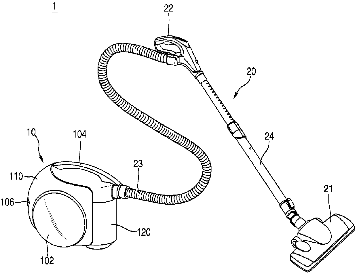
A technology for vacuum cleaners and vacuum cleaners, applied in the directions of vacuum cleaners, suction filters, suction nozzles, etc., can solve the problems of reduced suction force and reduced air flow of vacuum cleaners, and achieve the effects of reducing flow loss, improving suction performance, and improving suction efficiency.

Active Publication Date: 2018-09-28
LG ELECTRONICS INC
View PDF6 Cites 1 Cited by
  • Summary
  • Abstract
  • Description
  • Claims
  • Application Information

AI Technical Summary

Problems solved by technology

Based on the above-mentioned structure, in the vacuum cleaner of the prior art, when the sucked air flows into the pipe, flow loss occurs due to friction.
As a result, the flow rate of air flowing into the dust separator will be reduced, and the suction force of the vacuum cleaner will be reduced.

Method used


Image

  • Vacuum cleaner
  • Vacuum cleaner
  • Vacuum cleaner

Examples


Embodiment Construction

[0054] Hereinafter, some embodiments of the present invention will be described in detail with reference to the accompanying drawings. When assigning reference numerals to constituent elements in each drawing, the same constituent elements are assigned the same reference numerals as much as possible even if they are respectively shown in different drawings.

[0055] Also, terms such as first, second, A, B, (a), (b), etc. may be used in describing structural elements of the embodiments of the present invention. These terms are only for distinguishing the structural elements thereof from other structural elements, and are not intended to limit the nature, order or order, etc. of the corresponding structural elements. It should be pointed out that when it is stated in the description that a certain structural element is "connected", "joined" or "coupled" to another structural element, the structural element may be directly connected or coupled with another structural element, but...


PUM


Abstract

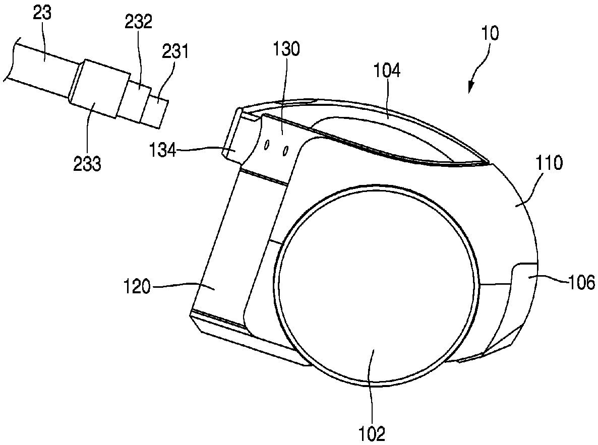
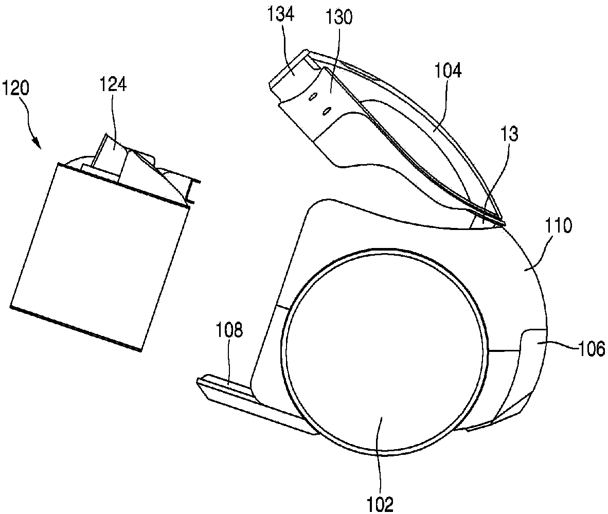
The present invention relates to a vacuum cleaner. The vacuum cleaner, according to one aspect, comprises: a cleaner main body which has a suction motor for generating suction force; and a suction hose which communicates with the cleaner main body and sucks in air and dust. The cleaner main body comprises: a main body part; a dust container which is provided to the main body part and has a suctionport through which dust sucked in through the suction hose is introduced, and a storage space in which the dust is collected; and a cover member which is provided with a connector having one side thereof connected with the suction hose, and which selectively shields at least one portion of the dust container, wherein, when the cover member shields one side of the dust container, the connector aligns in parallel with the direction in which air is introduced at the suction port.

Description

technical field [0001] The present invention relates to vacuum cleaners. Background technique [0002] Generally speaking, a vacuum cleaner is a device that uses a suction motor provided inside the main body to suck in dust and impurities that exist on the surface to be cleaned, and then filters the dust and impurities from the inside of the main body. [0003] The above-mentioned vacuum cleaners can be divided into: an upright (up-right) vacuum cleaner in which the suction nozzle is connected to the body and moves together with the body, and a horizontal (up-right) vacuum cleaner in which the suction nozzle is connected to the body through extension pipes, handles, hoses, etc. canister) type vacuum cleaner. [0004] Korean Laid-Open Patent Publication No. 10-2012-0004100 (publication date: January 12, 2012), which is a prior document, discloses a canister vacuum cleaner. [0005] The vacuum cleaner of the prior art disclosed in said prior document includes: a suction moto...

Claims


Application Information

Patent Timeline
Patent Type & Authority Applications(China)
IPC IPC(8): A47L9/00A47L9/10A47L9/02A47L9/16A47L9/32A47L5/36A47L9/28
CPCA47L5/362A47L9/1683A47L9/1691A47L9/242A47L9/0081A47L9/009A47L9/102A47L9/12A47L9/2805A47L9/2852A47L9/2857A47L9/2884
Inventor 孙正圭南普铉朴材容裵世焕
Owner LG ELECTRONICS INC
Learn More