Reversible rotary compressor

A two-way rotation, compressor technology, applied in compressors, irreversible cycle compression machines, rotary piston machines, etc., can solve problems such as low reliability of compressors and increased manufacturing costs

Inactive Publication Date: 2002-06-05
MITSUBISHI ELECTRIC CORP
View PDF1 Cites 3 Cited by
  • Summary
  • Abstract
  • Description
  • Claims
  • Application Information

AI Technical Summary

Problems solved by technology

Increased manufacturing cost, and the reliability of the compressor assembled in this way is not high

Method used


Image

  • Reversible rotary compressor
  • Reversible rotary compressor
  • Reversible rotary compressor

Examples


Embodiment 1

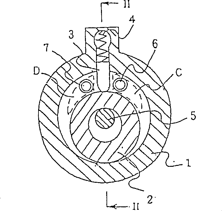
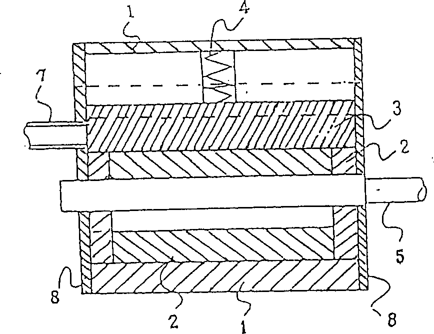
[0034] figure 1 A cross-sectional view shows a reversible rotary compressor according to a first embodiment of the present invention. The number 1 in the figure represents a cylinder; 2 is a rolling piston; 3 is a sliding plate; 4 is a spring for making the sliding plate 3 close to the rolling piston 2; 5 is the crankshaft of the rolling piston 2; C and D For the inlet / outlet, they are arranged in the space between the inner surface of the cylinder 1 and the outer surface of the rolling piston 2, and are symmetrically arranged on both sides of the sliding plate 3; The refrigerant is supplied to the inlet / outlet C or discharged from the inlet / outlet C; the inlet 7 is used as a refrigerant pipe for supplying the refrigerant to the inlet / outlet D or discharging the refrigerant from the inlet / outlet D. The refrigerant pipes 6 and 7 are closed by the rolling piston 2 when the rolling piston 2 reaches the top dead center, and are opened when it is at the bottom dead center.

[00...

Embodiment 2

[0047] As previously described, in Embodiment 1, the refrigerant pipes 6 and 7 connected to the inlet / outlet ports C and D are arranged on only one side wall 8 of the cylinder 1 . These refrigerant pipes can also be arranged as required, that is, the refrigerant pipe 6 connected to the inlet / outlet C is arranged on the side wall 8 of the cylinder 1, and the refrigerant pipe connected to the inlet / outlet D 7 is set on the other side wall 8 ( Figure 7 ).

[0048] In the refrigerant tubes thus arranged, the flow of refrigerant is unidirectional and thus smooth.

Embodiment 3

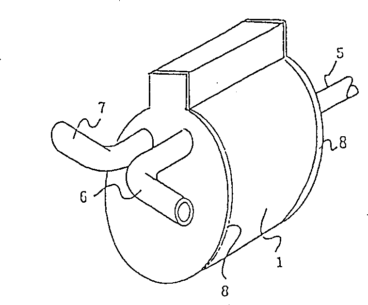
[0050] Figure 8 The perspective view of is showing the appearance of the reversible rotary compressor according to the third embodiment of the present invention. The refrigerant pipes 6 and 7 connected to the inlet / outlet ports C and D in this example are each connected to both walls of the cylinder 1 as shown in the figure.

[0051] This connection of the refrigerant tubes uniformly supplies the refrigerant to the cylinder 1, resulting in smooth compression of the refrigerant. In addition, the suction area is doubled to reduce the suction loss.


PUM


Abstract

The invention concerns a reversible rotary compressor which can compress refrigerant in either of the forward and reverse directions, without providing a valve mechanism in a closed container. In a reversible rotary compressor including a cylinder, a rolling piston, and a slide vane, two inlet / outlet ports are formed in a space between the outer surface of the rolling piston and the inner surface of the cylinder in a state that the two inlet / outlet ports are disposed on both sides of the slide vane. The two inlet / outlet ports are closed by the rolling piston when the rolling piston is positioned at the top dead center and fully opened when the rolling piston is positioned at the bottom dead center. Two refrigerant pipes, coupled with the inlet / outlet ports, are provided in the side wall of the cylinder. The two refrigerant pipes are closed by the rolling piston when the rolling piston is positioned at the top dead center and fully opened when the rolling piston is positioned at the bottom dead center.

Description

[0001] The technical field of the invention [0002] The present invention relates to a bidirectional rotary compressor in which the compressor itself can perform forward and reverse rotation, and a reversible refrigeration cycle using the bidirectional rotary compressor instead of a four-way valve. Background technique [0003] Figure 12 It is a common reversible rotary compressor disclosed in Unexamined Japanese Patent Application No. Sho 62-3196. The number 112 in the figure represents the motor rotor; 107 is a rotating shaft; 118 is a valve mechanism; 114 is the main bearing; 116 is the cylinder; the side note Pa represents the first refrigerant pipe; Pb represents the second refrigerant pipe ; 119a is an air inlet; 106 represents a closed container. [0004] The operation of the reversible rotary compressor of this structure will now be described. Figure 12 Among them, the rotor 112 is controlled to rotate the rotating shaft 107, and make the shaft 107 rotate forward o...

Claims


Application Information

Patent Timeline
Patent Type & Authority Patents(China)
IPC IPC(8): F04CF04C18/00F04C18/356F04C28/04F04C29/00F04C29/12F25B1/04
CPCF04C29/12F04C28/04F04C18/356
Inventor 松冈文雄山崎起助手塚与文望月哲哉田边义浩
Owner MITSUBISHI ELECTRIC CORP
Why Eureka
Try Eureka