Method for compacting the ballast bed of a track, and tamping unit

A ballast and track technology, applied in the field of tamping units for ballast compaction, can solve the problem that the ballast compaction degree cannot be obtained, and achieve the effects of uniform sleeper track bed, uniform compaction quality, and reduced wear and tear.

Active Publication Date: 2018-09-28
PLASSER & THEURER EXPORT VON BAHNBAUMASCHINEN GESELLSCHAFT MBH
View PDF6 Cites 5 Cited by
  • Summary
  • Abstract
  • Description
  • Claims
  • Application Information

AI Technical Summary

Problems solved by technology

An important disadvantage is that this ratio cannot draw any conclusions about the degree of compaction of the ballast

Method used


Image

  • Method for compacting the ballast bed of a track, and tamping unit
  • Method for compacting the ballast bed of a track, and tamping unit
  • Method for compacting the ballast bed of a track, and tamping unit

Examples


Embodiment Construction

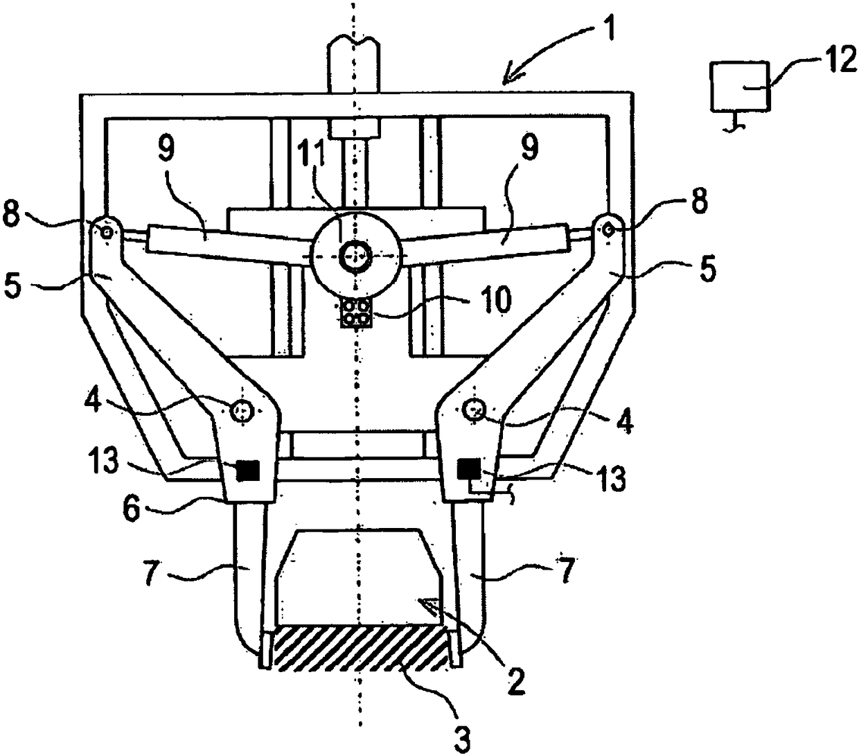
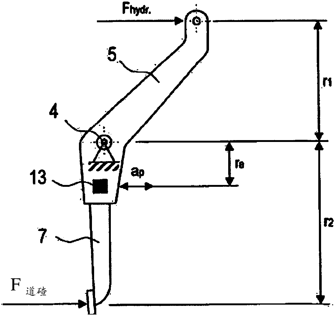
[0017] exist figure 1 The tamping unit 1 shown in a simplified manner is used for tamping the ballast 3 of the ballast bed below the track 2, and the tamping unit basically consists of two tamping rods 5, each of which can be Pivot about pivot axis 4 . At the lower end 6, these tamping rods 5 are respectively connected with a compacting tool or a tamping pick 7, which is provided for penetrating into the ballast 3, and the tamping rods 5 are connected at the upper end 8 is connected to the hydraulic squeeze driver 9.

[0018] Each extrusion drive 9 is mounted on an eccentric shaft 11 which can be rotated by the eccentric drive 10 . As a result, oscillatory oscillations are generated, which are transmitted to the ballast 3 to be compacted via the squeeze drive 9, the tamping rod 5 and the compacting tool 7. At the lower end 6 of each tamping rod 5 there is arranged an acceleration sensor 13 which is connected to the control unit 12 . Alternatively, however, the acceleration...


PUM


Abstract

Ballast (3) located below crossties of a track is compacted by plunging and closing compacting tools (7), which are caused to vibrate. The vibrations applied to the ballast (3) during the compacting process are recorded as a measure of the ballast compaction. Thus, a homogeneously compacted track can be achieved even in the case of differing ballast properties.

Description

technical field [0001] The invention relates to a method for compacting a ballast bed of a track by means of a compacting tool arranged to oscillate, and to a tamping unit for compacting ballast. Background technique [0002] A tamping unit for compacting track ballast is known from AT 513 973 B1. In this tamping unit, the position of the pressing cylinder pressing the compacting tool is detected by a displacement sensor. The squeeze cylinder is controlled by a path sensor. In order to achieve optimal ballast compaction, the oscillation amplitude and oscillation frequency of the compaction tool are changed according to the pressing position. [0003] AT 515 801 B1 describes mass values ​​for ballast hardness. In this case, the extrusion force of the extrusion cylinder is shown on the basis of the extrusion path, and a characteristic value is defined via the energy consumption. Therefore, the energy supplied to the ballast via the squeezing cylinder is considered as this ...

Claims


Application Information

Patent Timeline
Patent Type & Authority Applications(China)
IPC IPC(8): E01B27/13
CPCE01B27/17E01B2203/12E01B2203/127E01B27/13E01B27/16F17C7/04F17C2227/0142F17C2265/068F17C2265/07F17C2265/05E01B2203/028
Inventor J·霍夫斯坦特T·菲利普
Owner PLASSER & THEURER EXPORT VON BAHNBAUMASCHINEN GESELLSCHAFT MBH
Why Eureka
Try Eureka