Display device

A display device and image data technology, applied to static indicators, instruments, etc., can solve the problems of easy-to-see flicker and reduced image brightness

Inactive Publication Date: 2018-09-28
SHARP KK
View PDF14 Cites 0 Cited by
  • Summary
  • Abstract
  • Description
  • Claims
  • Application Information

AI Technical Summary

Problems solved by technology

At this time, the brightness of the image is greatly reduced, so flickering is easily seen

Method used


Image

  • Display device
  • Display device
  • Display device

Examples


no. 1 Embodiment approach >

[0101]

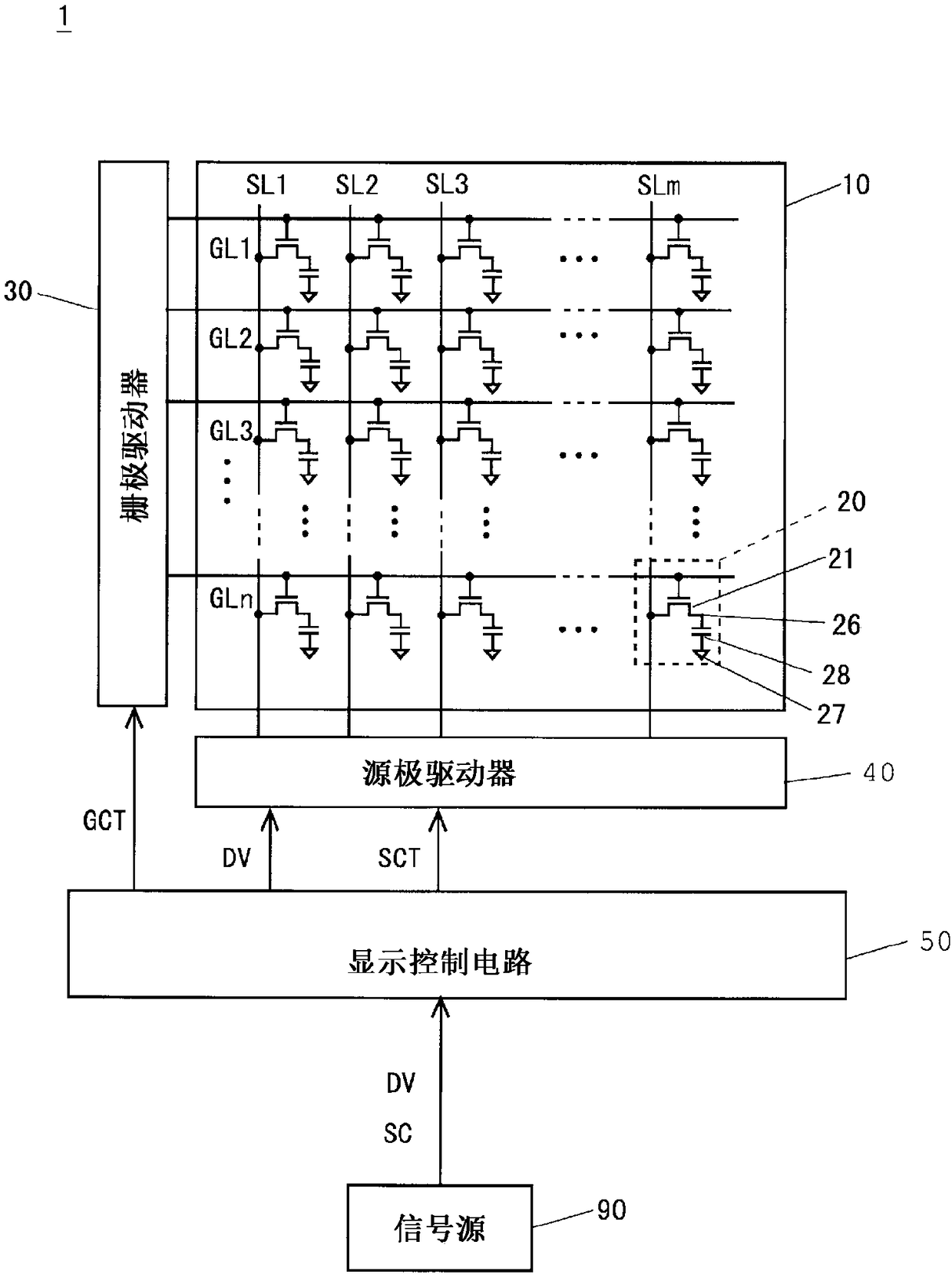
[0102] figure 1 It is a block diagram showing the configuration of the liquid crystal display device 1 according to the first embodiment of the present invention. like figure 1 As shown, the liquid crystal display device 1 includes a liquid crystal display panel 10 , a gate driver 30 as a scanning signal line driver, a source driver 40 as a data signal line driver, and a display control circuit 50 as a display control unit.

[0103] In the liquid crystal display panel 10, m source lines SL1 to SLm serving as video signal lines, n gate lines GL1 to GLn serving as scanning signal lines, and these source lines SL1 to SLm and gate lines GL1 are formed. The intersections of -GLn correspond to (m×n) pixel forming sections 20 arranged in a matrix. Each pixel forming portion 20 includes a TFT 21 whose gate terminal as a control terminal is connected to a gate line GL passing through a corresponding intersection and whose source terminal as a first conduction terminal is...

no. 2 Embodiment approach >

[0138] The configuration and the figure 1 The configuration of the liquid crystal display device 1 of the first embodiment shown is the same, and therefore a block diagram and description thereof are omitted. The liquid crystal display device of this embodiment performs BC driving and high-speed scanning in the immediately following driving period when the number of pause frames in the pause period is more than the predetermined number, but when the number of pause frames in the pause period is less than the predetermined number, BC drive and high-speed scanning are performed. No scans are performed.

[0139]

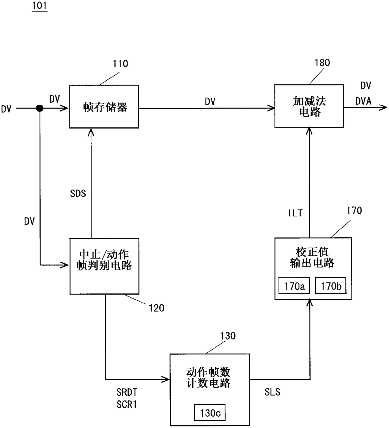
[0140] Figure 10 It is a block diagram showing the configuration of the correction circuit 102 included in the display control circuit of the liquid crystal display device of this embodiment. Figure 10 The correction circuit 102 is shown in the figure 2 The calibration circuit 101 shown further includes an idle frame number counting circuit 140 and a scanning s...

no. 3 Embodiment approach >

[0154] The configuration and the figure 1 The configuration of the liquid crystal display device of the first embodiment shown is the same, and therefore the block diagram and its description are omitted. When the image does not change from the idle period to the driving period, flicker is easily seen. Therefore, the liquid crystal display device of this embodiment performs BC driving and high-speed scanning in the immediately following driving period. However, flicker is not easily seen when the image changes, so neither BC drive nor high-speed scanning is performed.

[0155]

[0156] Figure 13 It is a block diagram showing the configuration of the correction circuit 104 included in the display control circuit of the liquid crystal display device of the present embodiment. Figure 13 The correction circuit 104 is shown in the Figure 10 The illustrated correction circuit 102 is provided with an image comparison circuit 150 instead of the stop frame number counting circ...


PUM


Abstract

Provided is a display device that makes flicker to be less easily visually recognized by suppressing a change in the brightness of an image in a shift from a pause period to a drive period. Regardlessof the number of paused frames in an immediately preceding pause period, and the presence or absence of a change in an image immediately after a shift from a pause period to a drive period, high-speed scanning is performed on first to third operating frames, and BC driving is performed on the first and second operating frames. Consequently, a change in the brightness of the image immediately after the shift from the pause period to the drive period can be suppressed in a short time, and therefore the occurrence of flicker to be visually recognized by a viewer is suppressed. Moreover, since the high-speed scanning is performed on the first to third operating frames, power consumption of a liquid crystal display device (1) can be reduced.

Description

technical field [0001] The present invention relates to a display device, in particular to a liquid crystal display device capable of pause driving. Background technique [0002] In recent years, development of small and lightweight electronic devices has been actively carried out. A liquid crystal display device mounted in such electronic equipment is required to have low power consumption. As one of the driving methods for reducing the power consumption of the liquid crystal display device, there is a driving method called "pause driving" in which the voltage of the image signal based on the image data is written by scanning the scanning signal line. (hereinafter, referred to as "image signal voltage") to display a moving image, there is provided a rest period in which writing is suspended by inactivating all the scanning signal lines to display a still image. In the pause drive, the operation of the gate driver and the source driver is stopped by not supplying control s...

Claims


Application Information

Patent Timeline
Patent Type & Authority Applications(China)
IPC IPC(8): G09G3/36G02F1/133G09G3/20
CPCG09G3/3648G09G2310/065G09G2320/0252G09G2320/0285G09G2340/16G09G3/36G09G3/20G09G3/3677G09G3/3688G09G2300/0842G09G2320/0247G09G2320/0271G09G2320/041G09G2330/021
Inventor 曾根琢矢须山达彦田中纪行植村健太郎
Owner SHARP KK
Why Eureka
Try Eureka