

Thin pancake machine
The technology of a pancake machine and an extruding mechanism is applied in the field of pancake machines for making pancakes, which can solve the problems of low degree of automation and labor consumption, and achieve the effects of good heat resistance and food safety.
- Summary
- Abstract
- Description
- Claims
- Application Information
AI Technical Summary
Problems solved by technology
Method used
Image

Examples
Embodiment 2
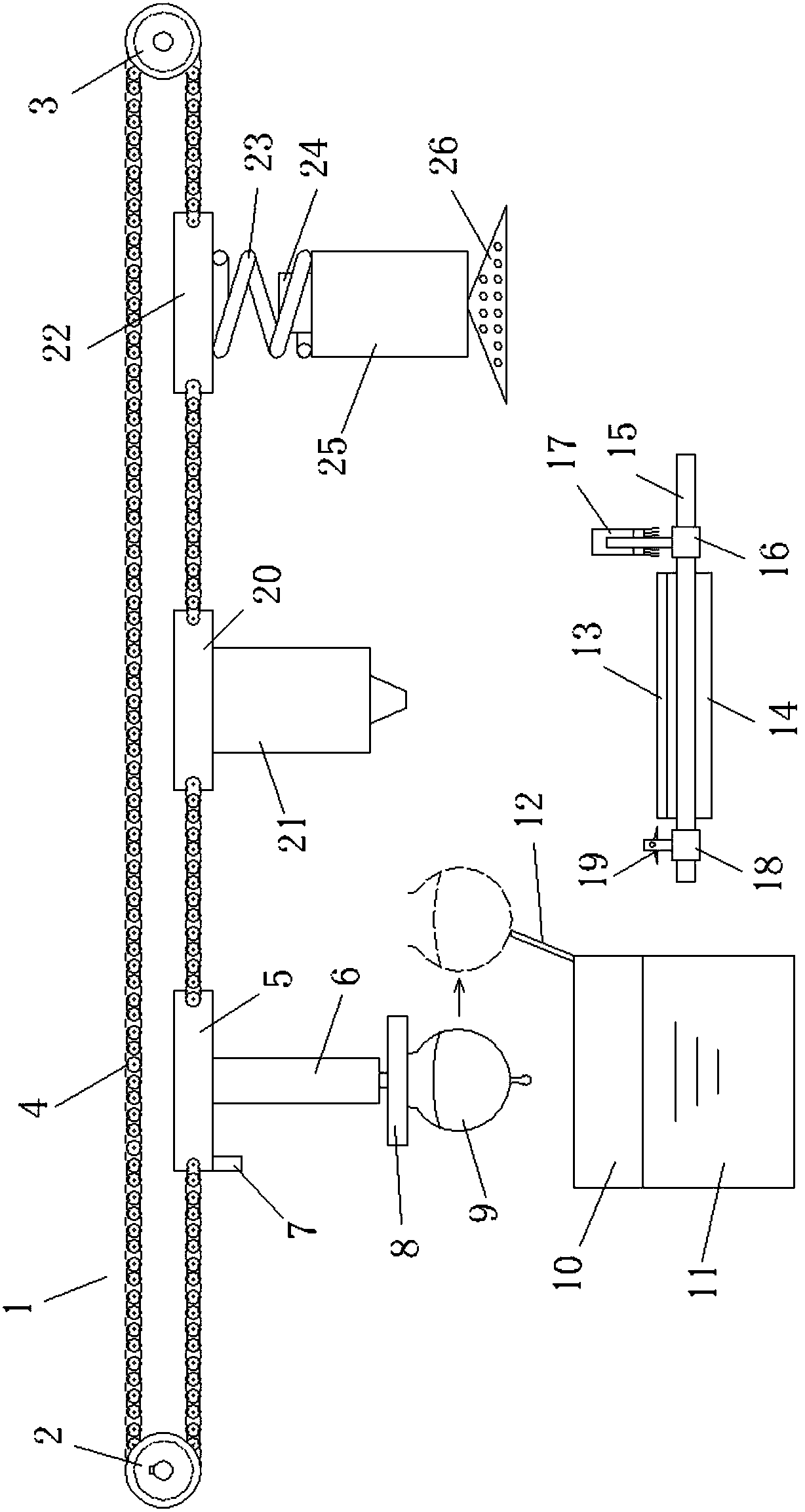
[0053] Such as Figure 6-8 As shown, the structural design of the pancake machine 120 in the pancake machine provided by this embodiment is different, and also includes: the ejector rod 130 and the jacking actuator;
[0054] A plurality of first shaft holes 121 are arranged on the plate 120;
[0055] The push rod 130 is telescopically and slidably arranged on the first shaft hole 121;
[0056] The jacking actuator is used to drive the ejector rod 130 to move up and down along the first shaft hole 121, so that the top of the ejector rod 130 protrudes from the upper edge of the first shaft hole 121 or retreats into the first shaft hole 121; the top of the ejector rod 130 extends When going out of the first shaft hole 121, the top of the push rod 130 protrudes from the upper surface of the griddle 120, forcing the cake body 160 above the griddle 120 to separate from the griddle 120.
[0057] The present embodiment also includes a base 120a and a first bracket 131; the cauldron ...
Embodiment 3
[0066] The structure of this embodiment is the same as that of Embodiment 2, the difference is that:
[0067] Such as Figure 10 As shown, when the top of the ejector rod 130 protrudes from the upper edge of the first shaft hole 121, the ejector rod 130 includes a protruding portion 130a protruding from the first shaft hole 121; the outer surface of the protruding portion 130a is provided with a blowing hole 133 , The ejector rod 130 is provided with a gas passage 134 inside, and the air blowing hole 133 is connected to the pressure gas source through the gas passage 134 and the gas pipeline. The gas pipeline is provided with a control switch and a controller for controlling gas on-off. Control switches and controllers are prior art and will not be repeated here. Wherein the pressure gas source preferably adopts a small air pump.
[0068] After the ejector pin 130 is lifted, the protruding part 130a lifts the cake body, and at the same time, the pressure gas source blows ai...
Embodiment 4
[0071] The structure of this embodiment is the same as that of Embodiment 3, the difference is that:
[0072] like Figure 11 As shown, a first shaft hole 121 and a second shaft hole 123 are provided on the plate 120 at the same time. like Figure 12 As shown, this embodiment also includes a pulping rod 150 and a pulping actuator, and a plurality of second shaft holes 123 are arranged on the plate 120; the pulping rod 150 is telescopically and slidably arranged in the second shaft hole 123;
[0073] The pulping actuator is used to drive the pulping rod 150 to move up and down along the second shaft hole 123, and then force the top of the pulping rod 150 to protrude from the upper edge of the first shaft hole 121 or retreat into the first shaft hole 121; When the top of 150 stretches out from the upper edge of the second shaft hole, the pulp outlet rod 150 includes a protrusion extending out of the second shaft hole; a pulp outlet hole 151 is provided on the outer surface of ...
PUM
 Abstract
Description
Claims
Application Information