Hardware polishing equipment

A technology for hardware and equipment, applied in the field of hardware polishing equipment, can solve the problems of inconvenient operation, heavy weight, uneven polishing surface, etc., and achieve the effects of reducing defects, fast polishing, and uniform force

Inactive Publication Date: 2018-10-02
嘉善卡勒机车零部件有限公司
View PDF7 Cites 1 Cited by
  • Summary
  • Abstract
  • Description
  • Claims
  • Application Information

AI Technical Summary

Problems solved by technology

[0003] At present, there are many types of polishing machines on the market, but many polishing machines have complex structures and ordinary polishing effects, and make t

Method used


Image

  • Hardware polishing equipment
  • Hardware polishing equipment
  • Hardware polishing equipment

Examples


Example Embodiment

[0020] In order to make the technical means, creative features, goals and effects achieved by the present invention easy to understand, the present invention will be further described below in conjunction with specific embodiments.

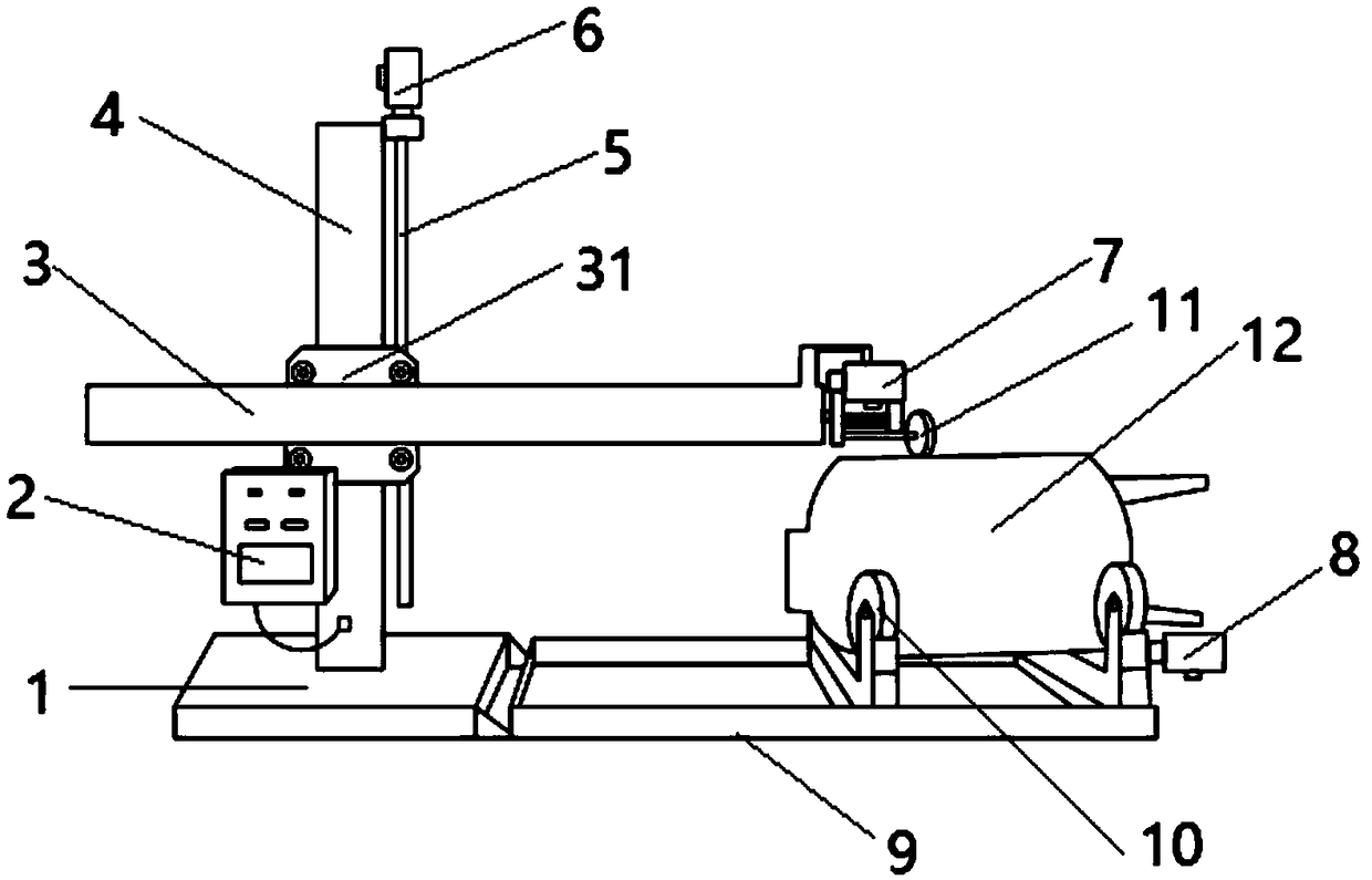
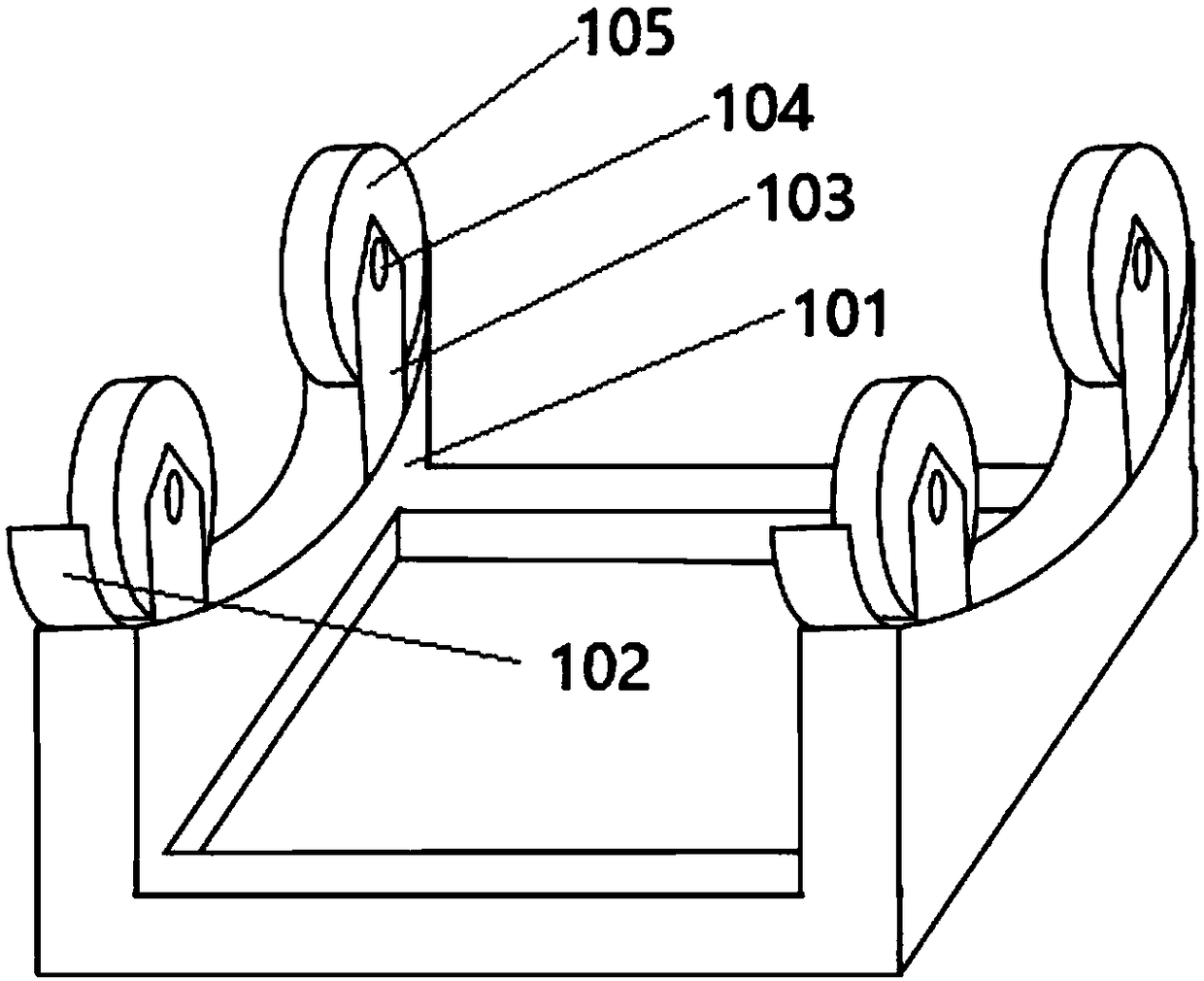
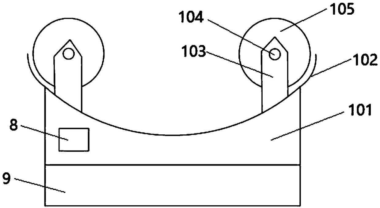
[0021] see Figure 1 to Figure 3 , a hardware polishing device according to the present invention, comprising a base 1, an electric box 2, a lifting rod 3, a fixed rod 4, a sliding rod 5, a polishing stone 11 and several motors, and the fixed rod 4 is vertically arranged on the base 1 Above, the lifting rod 3 is movably connected to the fixed rod 4, and the lifting rod 3 and the fixed rod 4 are perpendicular to each other; the sliding rod 5 is arranged on one side of the fixed rod 4 in parallel, and a The sliding base 31 is movably connected, and the sliding base 31 is fixedly connected with the lifting rod 3 , and the end of the lifting rod 3 is connected with the polishing stone 11 .

[0022] One side of described base 1 connects movable frame ...


PUM


Abstract

The invention discloses hardware polishing equipment which comprises a base, an electricity box, a lifting rod, a fixed bar, a slide bar, a polishing stone and a plurality of motors, wherein the fixedbar is vertically arranged on the base; the lifting rod is movably connected to the fixed bar; the slide bar is arranged on one side of the fixed bar in parallel; a sliding base movably connected ismounted between the fixed bar and the slide bar, and the sliding base is fixedly connected to the lifting rod; the polishing stone is connected to the end part of the lifting rod; one side of the baseis connected to a movable rack; a rolling rack is arranged on the movable rack; and the rolling rack comprises a fixed seat, a supporting rack, a safety hood, a roller and a rolling shaft; the fixedseat is fixed to the base through a first bolt; two ends of the rolling shaft are arranged on the supporting rack; and the safety hood is connected to the edge of an arc-shaped side plate. A polishedarticle is loaded by using the roller, so that the polishing area of the polished article is larger, and the polishing speed is higher; when the roller rolls at a uniform speed, the force of the polishing stone for polishing the polished article is more uniform.

Description

technical field [0001] The invention relates to the field of machinery, in particular to a machine for polishing appliances, in particular to a hardware polishing equipment. Background technique [0002] Polishing machines are often used for mechanical grinding, polishing and waxing. Its working principle is: the motor drives the sponge or wool polishing disc installed on the polishing machine to rotate at high speed. Due to the joint action of the polishing disc and the polishing agent and friction with the surface to be polished, it can achieve the effect of removing paint surface pollution, oxide layer and shallow marks. Purpose. Most of the polishing discs are infinitely variable, and can be adjusted at any time during construction. [0003] At present, there are many types of polishing machines on the market, but many polishing machines have complex structures and ordinary polishing effects, and make the polished objects prone to blemishes, uneven polished surfaces, e...

Claims


Application Information

Patent Timeline
IPC IPC(8): B24B29/02B24B47/12B24B41/02
Inventor 王峰
Owner 嘉善卡勒机车零部件有限公司
Why Eureka
Try Eureka