
Hydraulic drive joint for robots

A robot and hydraulic technology, applied in the direction of fluid pressure actuation device, manipulator, mechanical equipment, etc., can solve the problems of insensitive response and low torque density ratio, and achieve the effect of precise position control and precise torque control.

Active Publication Date: 2018-10-02
JIANGSU DREAMWELL DYNAMICS TECH CO LTD
View PDF11 Cites 14 Cited by
  • Summary
  • Abstract
  • Description
  • Claims
  • Application Information

AI Technical Summary

Problems solved by technology

At present, the existing robot joints basically use servo motor plus harmonic reducer or RV reducer. Although this structure has been widely used in the field of robotics, it cannot be denied that its torque density ratio is relatively low and the response is not sensitive enough.

Method used


Image

  • Hydraulic drive joint for robots
  • Hydraulic drive joint for robots
  • Hydraulic drive joint for robots

Examples


Embodiment Construction

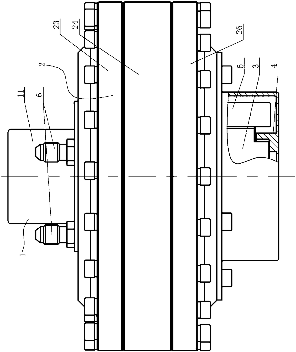
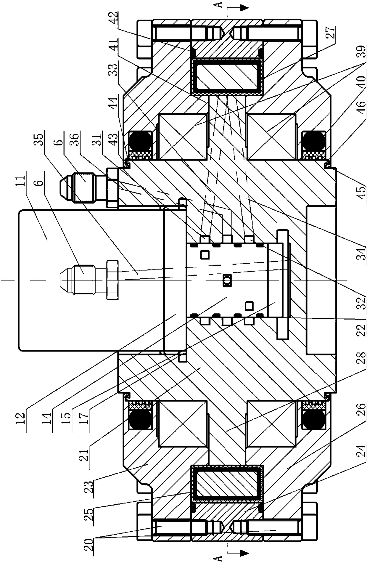
[0039] Hydraulically actuated joints for robots, see Figure 1-Figure 9 : It includes a hydraulic plug-in rotary direct drive valve 1, a vane swing cylinder 2, a valve body installation cavity 22 is prefabricated at one end of the center shaft 21 of the vane swing cylinder 2, and the shape of the valve body installation cavity 22 is according to the hydraulic plug-in rotation The shape of the insertion part of the direct drive valve 1 is made, the hydraulic plug-in rotary direct drive valve plug 1 is installed in the valve body installation cavity 22, and the driving motor 11 of the hydraulic plug-in rotary direct drive valve 1 is exposed to the central shaft 21;

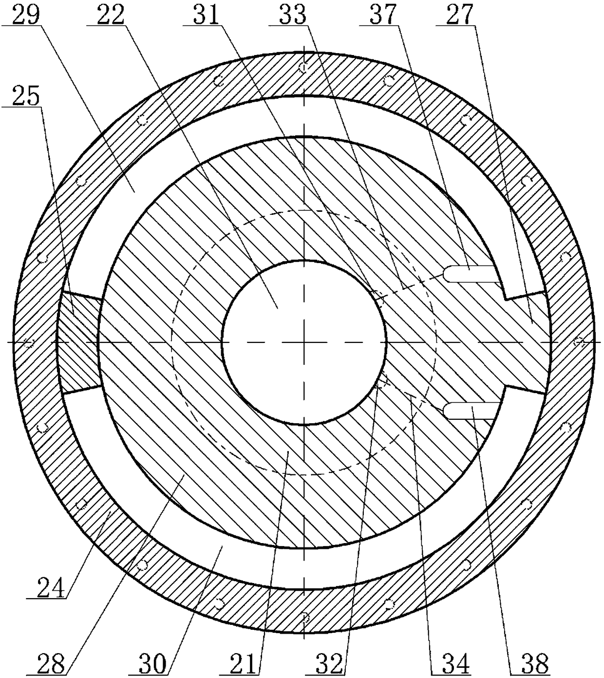
[0040] The blade swing cylinder 2 also includes an upper cover 23, a cylinder body 24, a fixed piece 25, a lower cover 26, and side convex blades 27. The central rotating shaft 21 is connected to the side convex blades 27 through the side convex ring 28, and the side convex blades 27 are in a zero position state. A ...


PUM


Abstract

The invention provides a hydraulic drive joint for robots, namely a robot joint based on the integration of a hydraulic plug-in rotary direct-drive valve and a blade rocking cylinder; a hydraulic actuator, an electrohydraulic servo valve, and detection elements, a position sensor and a pressure sensor, are modularly integrated and applied to the robot joint; the requirement for the development ofexisting robots can be met, and applicable range of the robots can also be widened. The hydraulic drive joint for robots comprises a threaded plug-in rotary direct-drive electrohydraulic servo valve,and a blade rocking hydraulic cylinder special for robot motion joints; the threaded plug-in rotary direct-drive electrohydraulic servo valve is abbreviated hereinafter as a hydraulic plug-in rotary direct-drive valve; the blade rocking hydraulic cylinder special for robot motion joints is abbreviated hereinafter as a blade rocking cylinder; a valve mounting cavity is pre-manufactured in one end of the center of a center spindle of the blade rocking cylinder; the shape of the valve mounting cavity is made according to the shape of an insert portion of the hydraulic plug-in rotary direct-drivevalve; the hydraulic plug-in rotary direct-drive valve is plugged in the valve mounting cavity.

Description

technical field [0001] The invention relates to the technical field of robot joints, in particular to hydraulically driven joints for robots. Background technique [0002] The robot joint is the basic component of the robot, and its performance directly affects the overall performance of the robot. With the continuous development of electromechanical technologies such as servo drive, control and sensing technology, robot joints present new characteristics and development trends, such as: large torque, high precision, sensitive response, miniaturization, mechatronics, standardization and modularization and other trends to adapt to the development of robot technology. At present, the existing robot joints basically use servo motor plus harmonic reducer or RV reducer. Although this structure has been widely used in the field of robotics, it cannot be denied that its torque density ratio is relatively low and the response is not sensitive enough. Because the hydraulic drive ha...

Claims


Application Information

Patent Timeline
Patent Type & Authority Applications(China)
IPC IPC(8): B25J17/02
CPCB25J17/0258B25J9/148F15B15/12F15B15/202F15B13/0406
Inventor 周小云
Owner JIANGSU DREAMWELL DYNAMICS TECH CO LTD
Learn More