Auxiliary equipment for building construction and with dust-proof and environment-friendly function
An auxiliary equipment and environmental protection technology, applied in the direction of buildings, building types, fences, etc., can solve the problems of long construction period, high cost, and many construction procedures, so as to save costs, prevent changes with the wind direction, and save the laying process Effect
- Summary
- Abstract
- Description
- Claims
- Application Information
AI Technical Summary
Problems solved by technology
Method used
Image
Examples
Embodiment 1
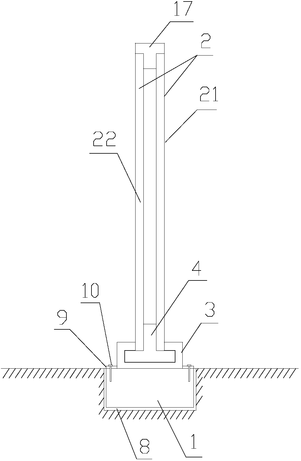
[0044] The present invention provides a construction auxiliary equipment with dustproof and environmental protection function, comprising a base 1 and a plurality of enclosure plates 2 connected in sequence, the base 1 is fixed in the ground, and the bottom end of the enclosure baffle 2 is fixed on the base On the seat 1, a C-shaped channel steel 3 is laid on the base 1 along the extending direction; the enclosure baffle 2 includes a first baffle 21 and a second baffle 22 with the same structure and size. 21 and the second baffle plate 22 are arranged in parallel, and the gap between the two opposite plate surfaces is greater than zero. 3; the two adjacent enclosure plates 2 are connected by a connecting column 5, and the axial bottom end of the connecting column 5 is detachably fixed on the C-shaped channel steel 3 through the connecting piece 4, and the cylindrical body of the connecting column 5 The side wall is provided with a slot 6 so that the radial cross section of the...
Embodiment 2
[0046] A further improvement is made on the basis of Example 1. A groove 8 is opened on the ground along the installation direction of the enclosure, and the remaining steel bars and concrete bricks of the construction site are laid in the groove 8, and cement is used to form the overall structure of the base 1. . The notch of the C-shaped channel steel 3 is downward, and the C-shaped channel steel 3 is provided with several connecting plates 9 along the long axis direction on the side wall near the bottom end. The through holes fix the connecting plate 9 on the base 1 . The first baffle 21 and the second wind baffle 22 are filled with sound insulation materials, such as activated carbon sound absorption materials.
Embodiment 3
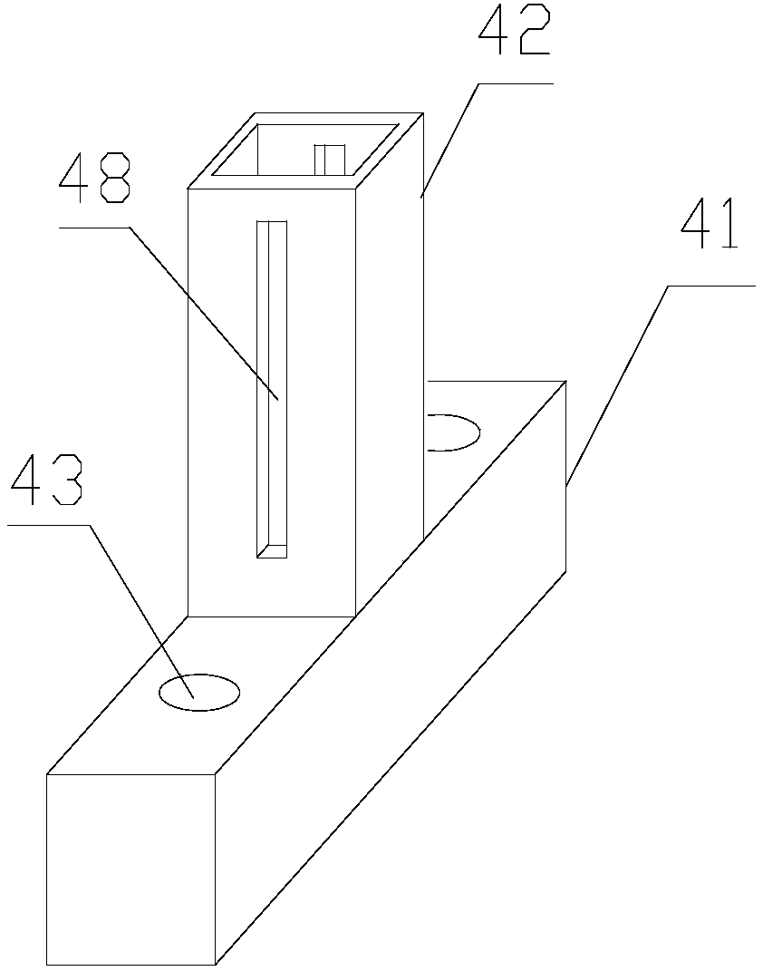
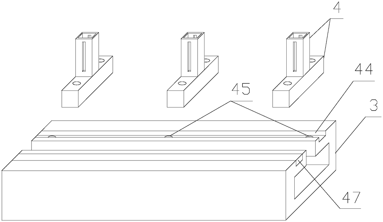
[0048] Further improvement on the basis of Embodiment 2, the connecting piece 4 is a T-shaped structure composed of a cross bar 41 and an upright column 42 integrally; the upright column 42 is placed on two opposite first baffles 21 and second baffles Between the plates 22, and the bottom ends of the first baffle 21 and the second baffle 22 can be detached and fixed on the column 42; the cross bar 41 is embedded in the C-shaped channel steel 3, and the axial direction of the cross bar 41 The radial direction of the C-shaped channel steel 3 is arranged in parallel, the transverse rod 41 is provided with a mounting threaded hole 43, and the top of the C-shaped channel steel 3 is provided with a mounting groove 44 along the long axis direction. The countersunk head bolt 46 penetrates the installation through hole 45 and then is screwed into the installation threaded hole 43 to realize the detachable connection between the connector 4 and the C-shaped channel steel 3 ; and the inst...
PUM
 Abstract
Description
Claims
Application Information
 - R&D
- Intellectual Property
- Life Sciences
- Materials
- Tech Scout
- Unparalleled Data Quality
- Higher Quality Content
- 60% Fewer Hallucinations
Browse by: Latest US Patents, China's latest patents, Technical Efficacy Thesaurus, Application Domain, Technology Topic, Popular Technical Reports.
© 2025 PatSnap. All rights reserved.Legal|Privacy policy|Modern Slavery Act Transparency Statement|Sitemap|About US| Contact US: help@patsnap.com


