Bearing cooling water flow condition monitoring device

A monitoring device and cooling water technology, applied in the components of the pumping device for elastic fluid, pump control, non-variable-capacity pump, etc., can solve the problems of dust removal fan bearing damage, low work efficiency, damage to fan bearing bushes, etc. , to achieve the effect of improving reliability and improving work efficiency

Inactive Publication Date: 2018-10-02
新锐咨询(辽宁)有限公司
View PDF0 Cites 0 Cited by
  • Summary
  • Abstract
  • Description
  • Claims
  • Application Information

AI Technical Summary

Problems solved by technology

[0003] The circulating water pump of the dust removal fan fails, causing the cooling water of the dust removal fan bearing to be cut off, resulting in high temperature in the bearing and damaging the fan bearing bush, which affects the normal operation of the dust removal fan
With the continuation and aging of the circulating water pump of the dust removal fan, the scale generated in the pump body during the operation will often cause damage to the blades of the circulating water pump, and the wear of the motor will affect the normal operation of the circulating water pump. In severe cases, the circulation of the circulating water is interrupted, and the bearing of the dust removal fan is damaged due to lack of normal cooling, which affects the dust removal of the dust removal fan.
The traditional circulating water pump failure judgment can only rely on manual uninterrupted patrol to observe the cooling water recovery pipe and the cooling water condition in the cooling water tank. Although this method is relatively reliable, the work efficiency is low, and it cannot be ruled out that it cannot be found in time due to other interference factors. Fault

Method used


Image

  • Bearing cooling water flow condition monitoring device

Examples


Embodiment Construction

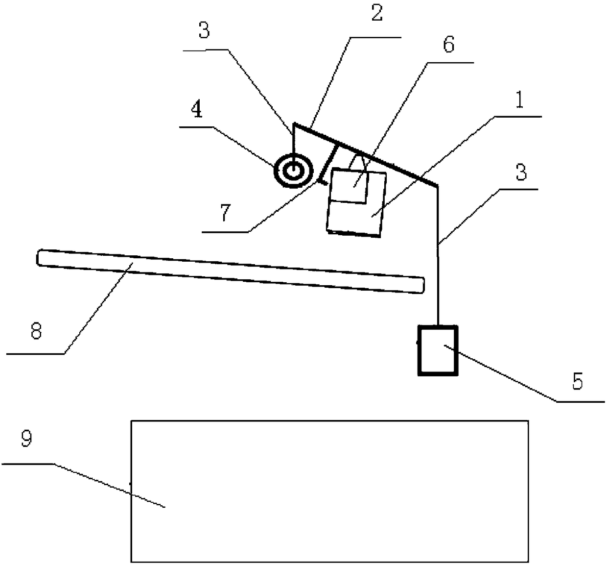
[0010] Such as figure 1 As shown, a bearing cooling water flow monitoring device includes a support frame 1, a balance beam 2, a suspension wire 3, a counterweight 4, a water collection bucket 5, a travel switch 6, a flashing light and a trigger lever 7. The support frame 1 is rotationally connected to the middle of the balance beam 2, the counterweight 4 and the water collection bucket 5 are respectively installed on both ends of the balance beam 2 through the hanging wire 3, and the travel switch 6 is installed on The side of the support frame 1, the flashlight is connected with the travel switch 6, the trigger lever 7 is installed on the balance beam 2 near the side of the counterweight 4, the trigger lever 7 The end faces the travel switch 6; the bottom of the water collection bucket 5 is provided with a mesh, the cooling water in the cooling water recovery pipe 8 flows into the water collection bucket 5, and the water collection bucket 5 is placed in the cooling water tan...


PUM


Abstract

The invention relates to a monitoring device, in particular to a bearing cooling water flow condition monitoring device. According to the technical scheme, the device comprises a supporting frame, a balance beam, hanging wires, a balancing weight, a water collecting barrel, a travel switch, a flash lamp and a triggering rod, the upper end of the supporting frame is rotationally connected with themiddle of the balance beam, the balancing weight and the water collecting barrel are installed at the two ends of the balance beam through the hanging wires respectively, the travel switch is installed on the side face of the supporting frame, the flash lamp is connected with the travel switch, the triggering rod is installed on one side, close to the balancing weight, of the balance beam, the endof the triggering rod is opposite to the travel switch, net holes are formed in the bottom of the water collecting barrel, cooling water in a cooling water recovery pipe flows into the water collecting barrel, and the water collecting barrel is installed and placed above a cooling water tank. According to the bearing cooling water flow condition monitoring device, a fault alarm signal can be automatically sent out when the supply of the bearing cooling water is cut off, so that full-automatic monitoring is carried out.

Description

technical field [0001] The invention relates to a monitoring device, in particular to a monitoring device for bearing cooling water flow. Background technique [0002] The dust removal fan is an important part of electrostatic dust removal and is the source of power. The fan is a machine that relies on the input mechanical energy to increase the gas pressure and discharge the gas. It is a driven fluid machine. For the main heat-generating parts during its operation, such as the friction between the shaft and the bearing, the circulating water is used to cool the heat-generating parts, so as to ensure the normal operation of the dust removal fan. [0003] The circulating water pump of the dust removal fan fails, causing the cooling water of the dust removal fan bearing to be cut off, resulting in high temperature in the bearing and damaging the fan bearing bush, which affects the normal operation of the dust removal fan. With the continuation and aging of the circulating wa...

Claims


Application Information

Patent Timeline
Patent Type & Authority Applications(China)
IPC IPC(8): F04D27/00F04D29/58
CPCF04D27/001F04D27/008F04D29/5846
Inventor 曹玉坤
Owner 新锐咨询(辽宁)有限公司
Why Eureka
Try Eureka